Service Modes, Error Codes, and Fault Finding
EN 30 Q522.2HE LA5.
2010-Jun-30
5.5 Service Tools
5.5.1 ComPair
Introduction
ComPair (Computer Aided Repair) is a Service tool for Philips
Consumer Electronics products. and offers the following:
1. ComPair helps to quickly get an understanding on how to
repair the chassis in a short and effective way.
2. ComPair allows very detailed diagnostics and is therefore
capable of accurately indicating problem areas.
Knowledge about I
2
C or UART commands is not needed,
because ComPair takes care of this.
3. ComPair speeds up the repair time since it can
automatically communicate with the chassis (when the uP
is working) and all repair information is directly available.
4. ComPair features TV software upgrade possibilities.
Specifications
ComPair consists of a Windows based fault finding program
and an interface box between PC and the (defective) product.
The (new) ComPair II interface box is connected to the PC via
an USB cable. For the TV chassis, the ComPair interface box
and the TV communicate via a bi-directional cable via the
service connector(s).
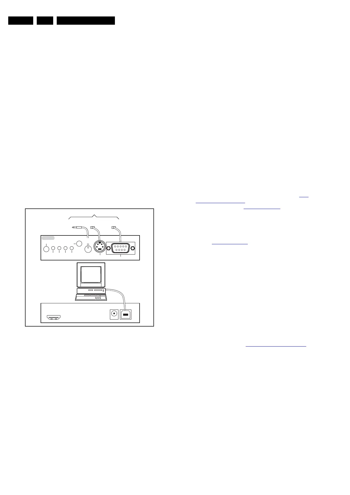
How to Connect
This is described in the ComPair chassis fault finding database.
Figure 5-13 ComPair II interface connection
Caution: The way of connection for this chassis is different
compared to the other Q52x chassis! This chassis uses UART
communication instead of RS232 which means that the voltage
levels are different. When this chassis is connected with a
ComPair RS232 cable, this could result in damaging the TV!
Therefore, it is compulsory to use ComPair II interface
together with the below mentioned Jack/Jack cable.
How to Order
ComPair II order codes:
• ComPair II interface: 3122 785 91020.
• The latest ComPair software can be found on the Philips
Service website.
• ComPair Jack/Jack cable: 3138 188 75051.
Note: If problems are encountered, contact the local support
desk.
5.5.2 LVDS Tool
Support of the LVDS Tool has been discontinued.
5.6 Error Codes
5.6.1 Introduction
The error code buffer contains all detected errors since the last
time the buffer was erased. The buffer is written from left to
right, new errors are logged at the left side, and all other errors
shift one position to the right.
When an error occurs, it is added to the list of errors, provided
the list is not full. When an error occurs and the error buffer is
full, then the new error is not added, and the error buffer stays
intact (history is maintained).
To prevent that an occasional error stays in the list forever, the
error is removed from the list after more than 50 hrs. of
operation.
When multiple errors occur (errors occurred within a short time
span), there is a high probability that there is some relation
between them.
Basically there are three kinds of errors:
• Errors detected by the Stand-by software. These errors
will always lead to protection and an automatic start of the
blinking LED for the concerned error (see section The
Blinking LED Procedure). In these cases SDM can be used
to start up (see section Stepwise Start-up
). Note that it can
take up to 90 seconds before the TV goes to protection and
starts blinking the error (e.g. error 53)
• Errors detected by main software that lead to
protection. In this case the TV will go to protection and the
front LED should also blink the concerned error. See also
section Extra Information
. For this chassis only error 63 is
a protection error detected by main software.
• Errors detected by main software that do not lead to
protection. In this case the error will be logged into the
error buffer and can be read out via ComPair, via blinking
LED method, or in case a picture is displayed, via SAM.
5.6.2 How to Read the Error Buffer
Use one of the following methods:
• On screen via the SAM (only if a picture is displayed). E.g.:
– 00 00 00 00 00: No errors detected
– 06 00 00 00 00: Error code 6 is the last and only
detected error
– 09 06 00 00 00: Error code 6 was first detected and
error code 9 is the last detected error
• Via the blinking LED procedure (when no picture is
displayed). See section How to Clear the Error Buffer
.
•Via ComPair.
• Via CSM. when CSM is activated the blinking LED
procedure will start and the CSM content will be written to
a USB stick (if present).
5.6.3 How to Clear the Error Buffer
Use one of the following methods:
• By activation of the “RESET ERROR BUFFER” command
in the SAM menu.
• With a normal RC, key in sequence “MUTE” followed by
“062599” and “OK”.
• If the content of the error buffer has not changed for 50+
hours, it resets automatically.
5.6.4 Error Buffer
In case of non-intermittent faults, clear the error buffer before
beginning the repair (before clearing the buffer, write down the
10000_036_090121.eps
091118
TO
UART SERVICE
CONNECTOR
TO
UART SERVICE
CONNECTOR
TO
I
2
C SERVICE
CONNECTOR
TO TV
PC
HDMI
I
2
C only
Optional power
5V DC
ComPair II Developed by Philips Brugge
RC out
RC in
Optional
Switch
Power ModeLink/
Activity
I
2
C
ComPair II
Multi
function
RS232 /UART