Mechanical Instructions
EN 12 TPS10.1L LA4.
2013-Apr-26
back to
div. table
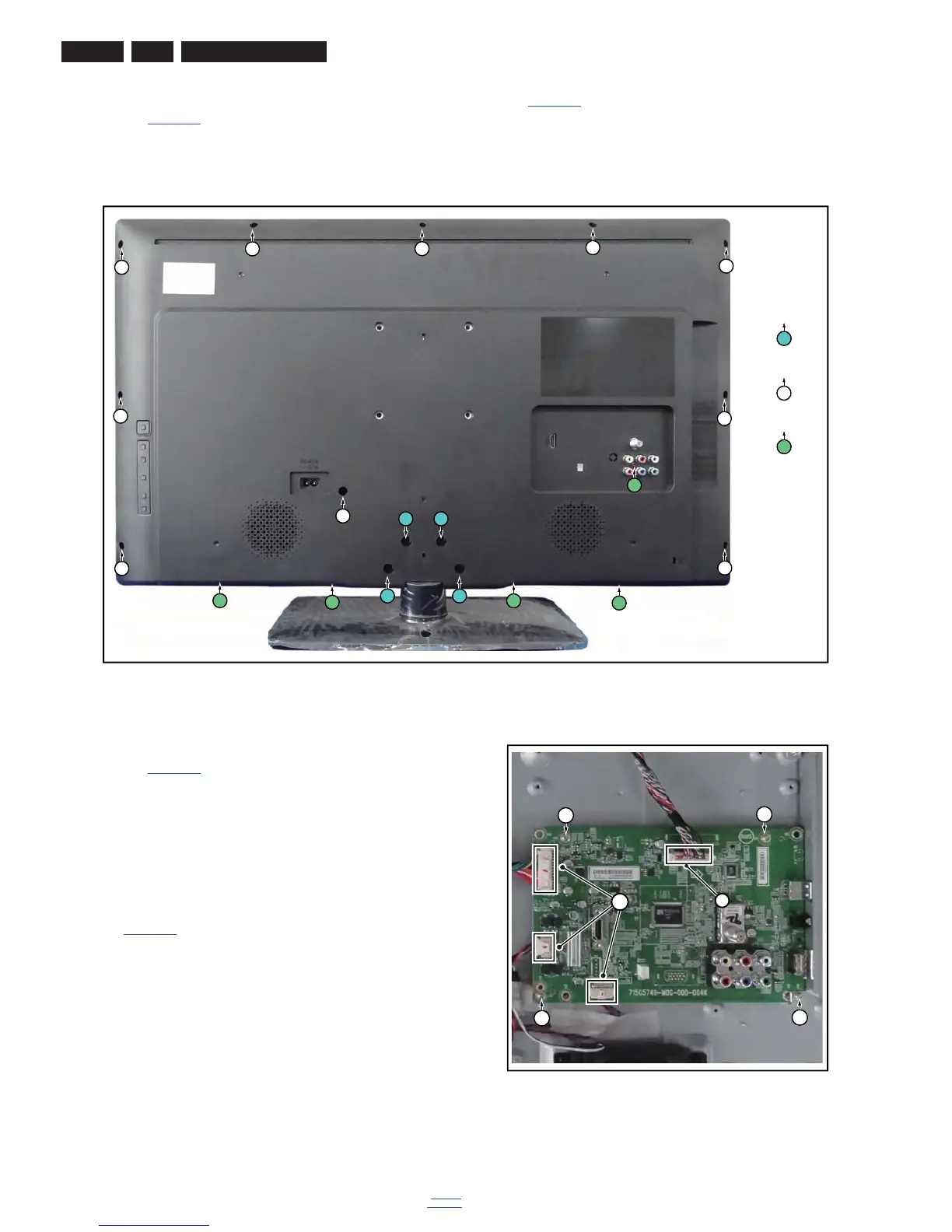
4.3.1 Rear Cover
Refer to Figure 4-4
for details.
Warning: Disconnect the mains power cord before removing
the rear cover.
1. Remove fixation screws [1] that secure the base assy, pull
out the base assy from the set. Then remove the fixation
screws [2], [3]that secure the rear cover. Refer to
Figure 4-4
for details.
2. Gently lift the rear cover from the TV. Make sure that wires
and cables are not damaged while lifting the rear cover
from the set.
Figure 4-4 Rear cover removal
4.3.2 Small Signal Board (SSB)
Refer to Figure 4-5
for details.
Caution: it is mandatory to remount all different screws at their
original position during re-assembly. Failure to do so may result
in damaging the SSB.
1. Release the clips from the LVDS connector that connect
with the SSB [1].
Caution: be careful, as these are very fragile connectors!
2. Unplug all other connectors [2].
3. Remove all the fixation screws from the SSB [3].
4. The SSB can now be shifted from side connector cover,
then lifted and taken out of the I/O bracket. Refer to
Figure 4-5
for details.
Figure 4-5 SSB removal