Mechanical Instructions
EN 18 L11M1.1L LA4.
2011-Jun-24
back to
div. table
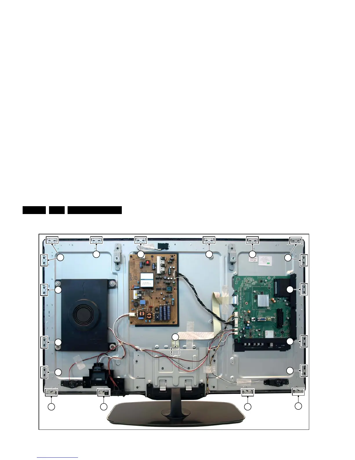
Figure 4-14 LCD Panel removal -2-
4.5 Set Re-assembly
To re-assemble the whole set, execute all processes in reverse
order.
Notes:
• While re-assembling, make sure that all cables are placed
and connected in their original position. See Figure 4-15
• Pay special attention not to damage the EMC foams in the
set. Ensure that EMC foams are mounted correctly.
Figure 4-15 Flat Foil Cable (FFC) precautions
Proper FFC insertion: Silver line is not
visible when connector lock is closed
Improper FFC insertion: Silver line is
visible when connector lock is closed
Panel
Thinner blue FFC supporting
tape belong to Panel side
Thicker blue FFC supporting
tape belong to SSB side
TCON
19130_007_110426.eps
110426