Mechanical Instructions
EN 17L11M1.1L LA 4.
2011-Jun-24
back to
div. table
4.4.4 Stand removal
1. Remove the four fixation screws.
2. Take the stand out in a downwards direction.
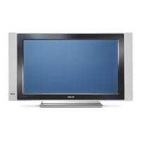
4.4.5 Stand bracket removal
Refer to Figure 4-10
for details.
Caution: it is mandatory to remount all different screws at their
original position during re-assembly. Be sure to put the set in
the Service Position.
1. Remove the fixation screws [1], [2].
2. Take the Stand bracket out.
Figure 4-10 Stand bracket removal
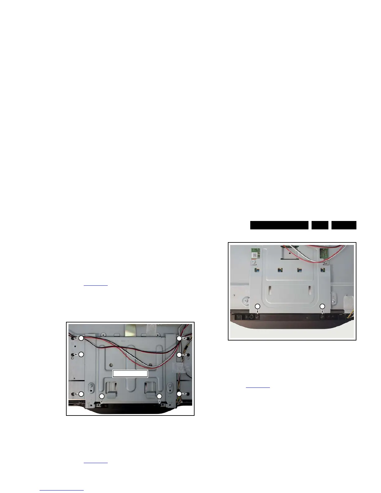
4.4.6 Power switch and mains plug
Refer to Figure 4-11
for details.
1. Unplug the connector from the PSU.
2. The switch and mains inlet can be removed by lifting the
catches with a screwdriver [1] and sliding them out [2].
When defective, replace the power switch and mains plug
assembly.
Figure 4-11 Power switch and mains plug removal
4.4.7 IR/LED/Keyboard
Refer to Figure 4-12
for details.
1. Remove the stand bracket as described earlier.
2. Remove the screws [1] that connect the IR/LED/Keyboard
to the bezel.
When defective, replace the whole unit.
Figure 4-12 IR/LED/Keyboard removal
4.4.8 LCD Panel
Refer to Figure 4-14
for details.
1. Remove the SSB as described earlier.
2. Remove the PSU as described earlier.
3. Remove the stand as described earlier.
4. Remove the stand bracket as described earlier.
5. Remove the Power switch and mains plug as described
earlier and remove the plastic subframe.
6. Remove the speakers.
7. Remove all tapes that secure any cable and remove the
cables from the set.
8. Release the clips from the LVDS flat
foil connector [1].
Caution: be careful, as these are very fragile cables and
connectors! Take the flat foil out of it’s connector.
9. Release the metal clips [2] at the top, sides and bottom of
the panel that secure the LCD panel with the bezel and
remove the clips from their position. Be careful not to break
the plastic catches [3] that secure the metal brackets.
10. Lift the LED Panel from the bezel.
When defective, replace the whole unit.
Figure 4-13 LCD Panel removal -1-