Mechanical Instructions
EN 16 L11M1.1L LA4.
2011-Jun-24
back to
div. table
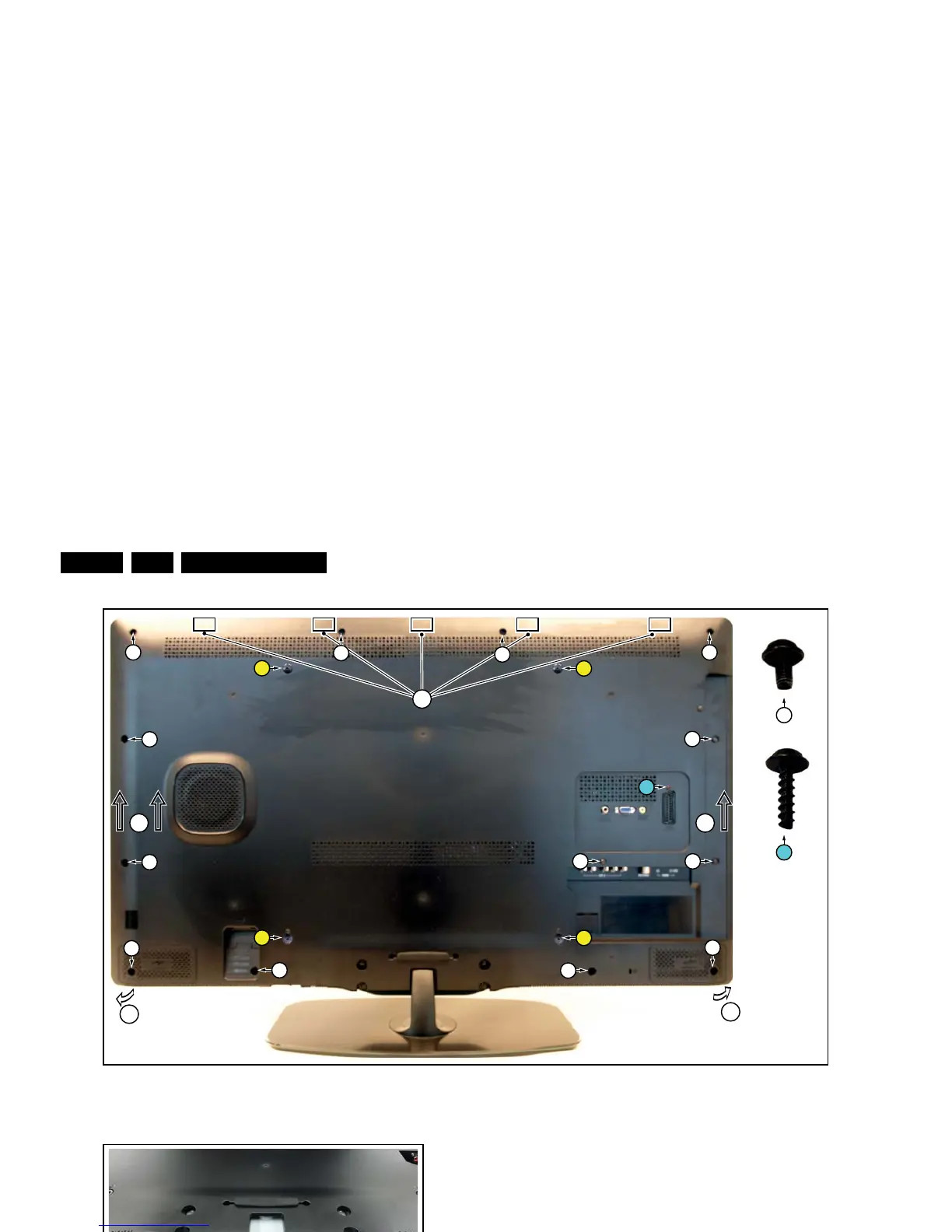
Figure 4-7 Rear cover removal -1-
Figure 4-8 Rear cover removal -2-
Figure 4-9 Rear cover removal -3-
4.4.2 Small Signal Board (SSB)
Caution: it is mandatory to remount all different screws at their
original position during re-assembly. Failure to do so may result
in damaging the SSB.
1. Release the clips from both the LVDS Flat Foil connectors
that connect with the SSB.
Caution: be careful, as these are very fragile connectors!
Take the flat foils out of their connectors.
2. Unplug all other connectors.
3. Remove all fixation screws from the SSB. Note that one
screw is located below the upper flat foil cable.
4. Take out the SSB together with side and bottom I/O
bracket.
5. Remove the screws between the bottom Y-Pb and L-R
audio connectors.
6. Remove the side and bottom I/O bracket from the SSB.
Note that these parts are kept in place by very fragile clips.
Release those clips gently!
4.4.3 Power Supply Unit (PSU)
Caution: it is mandatory to remount all different screws at their
original position during re-assembly. Failure to do so may result
in damaging the PSU.
1. Release the tape from the Power board cables.
2. Unplug power connectors from the SSB, as it is not unplug-
able at the PSU itself (soldered connector).
3. Unplug both other connectors from the PSU.
4. Remove all fixation screws from the PSU.
5. The PSU can be taken out of the set now.
When defective, replace the whole unit.