Mechanical Instructions
EN 16 Q552.1L LA4.
2010-Dec-29
back to
div. table
4. Remove the connectors [4] on the IR/LED board.
4.4.7 Keyboard Control Board
Refer to Figure 4-23
for details.
1. Unplug the connector on the IR & LED board that leads to
the Keyboard Control board as described earlier.
2. Release the cable from its clamps.
3. Release the clip on top of the unit [1] and take the unit out.
When defective, replace the whole unit.
Figure 4-15 Keyboard Control board
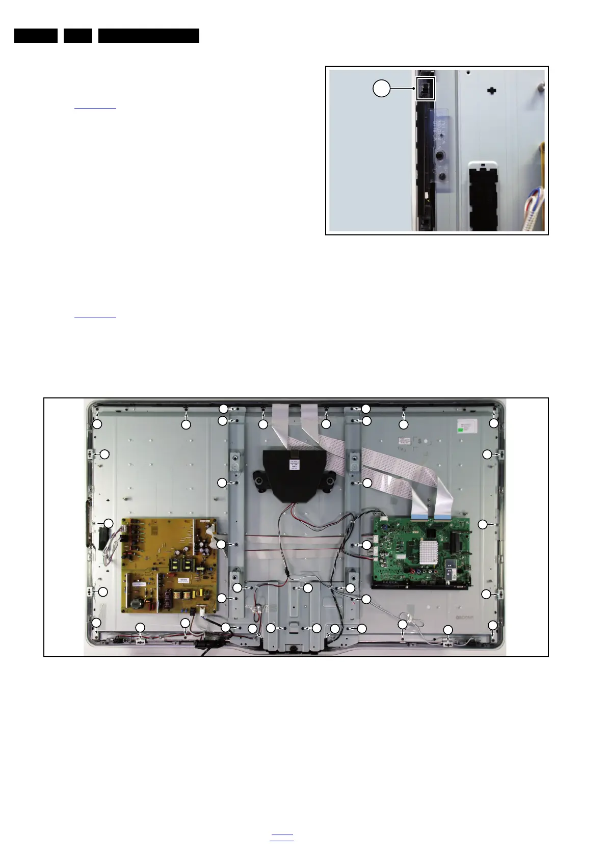
4.4.8 LCD Panel
Refer to Figure 4-24
for details.
1. Remove the stand as described earlier.
2. Remove the brackets [1].
3. Remove the stand support [2].
4. Remove the central subwoofer as described earlier.
5. Remove the tweeters as described earlier.
6. Remove the mains switch as described earlier.
7. Remove the IR & LED board as described earlier.
8. Remove the keyboard control board as described earlier.
9. Remove the clamps [3].
10. Remove the flare.
11. Remove all remaining screws [4].
Now the LCD Panel can be lifted from the front cabinet.
Figure 4-16 LCD Panel
4.5 Assy/Panel Removal da Vinci Styling
(6000 series)
The instructions below apply to the LC9.3L LA chassis
(32PFL6605D/xx), but are similar for other models.
18770_145_100216.eps
100217
1
18770_146_100216.eps
100407
1
1
1
1
1
2
2
2
2
2
2
1
1
1
1
1
2
4
4
4
4
4
4
3
3
4
3
4
4
4
3
4
3
4
3
4
4