Mechanical Instructions
EN 15Q552.1L LA 4.
2010-Dec-29
back to
div. table
4.4.2 Speakers
Tweeters
Each tweeter unit is mounted with one screw.
When defective, replace the whole unit.
Subwoofer
The central subwoofer is located in the centre of the set, and is
mounted with two screws.
When defective, replace the whole unit.
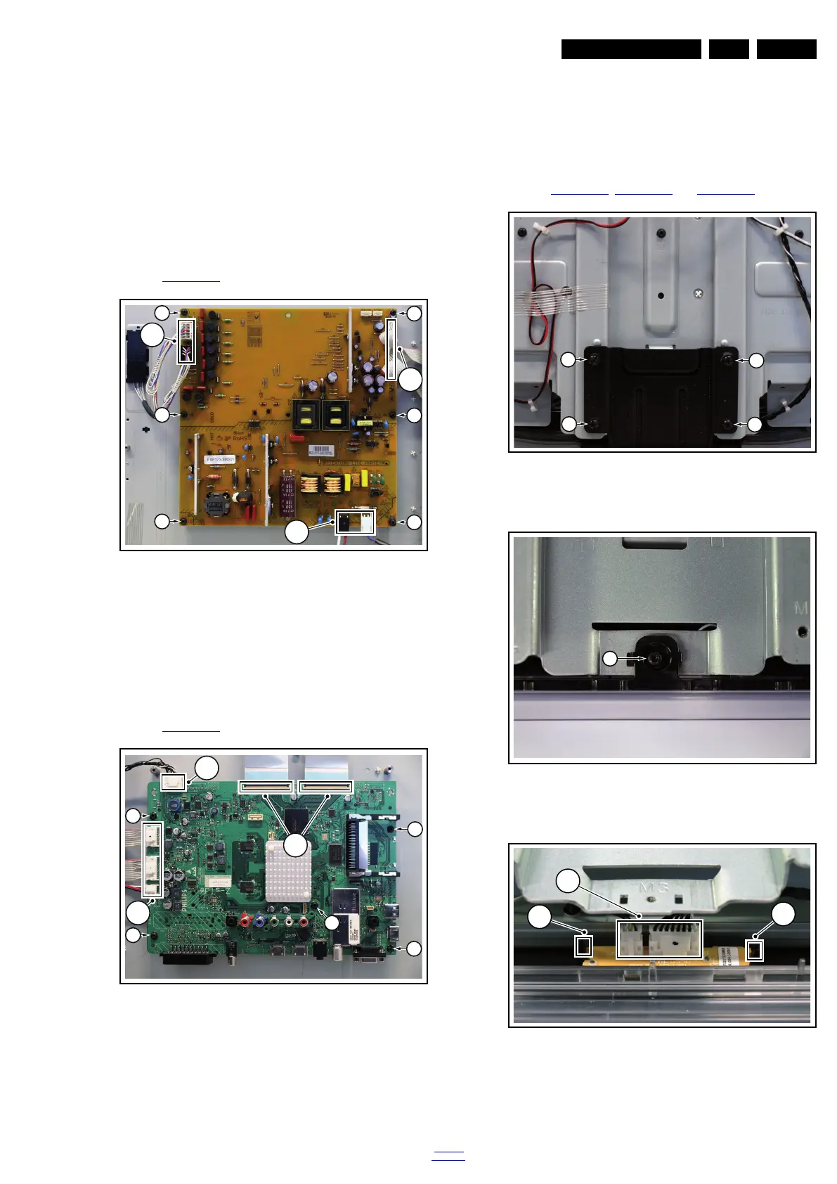
4.4.3 Main Power Supply
Refer to Figure 4-18
for details.
Figure 4-10 Main Power Supply
1. Unplug all connectors [1].
2. Remove the fixation screws [2].
3. Take the board out.
When defective, replace the whole unit.
4.4.4 Small Signal Board (SSB)
Refer to Figure 4-19
for details.
Figure 4-11 SSB
1. Unplug all connectors [1] and [2].
2. Remove the fixation screws [3].
3. Take the board out.
When defective, replace the whole unit.
4.4.5 Mains Switch
The mains switch is mounted on the front bezel with two
screws.
4.4.6 IR & LED Board
Refer to Figure 4-20
, Figure 4-21 and Figure 4-22 for details.
Figure 4-12 IR & LED Board -1-
Figure 4-13 IR & LED Board -2-
Figure 4-14 IR & LED Board -3-
1. Remove the stand [1].
2. Remove the IR & LED board cover [2].
3. Release the clips [3] that secure the IR & LED board.
18770_140_100215.eps
100217
1
1
1
2
2
2
2
2
2
18770_141_100215.eps
100217
2
2
1
3
3
3
3
3
18770_142_100215.eps
100215
1
1
1
1
18770_143_100215.eps
100215
2
18770_144_100215.eps
100215
4
3
3