Mechanical Instructions
EN 18 Q552.1L LA4.
2010-Dec-29
back to
div. table
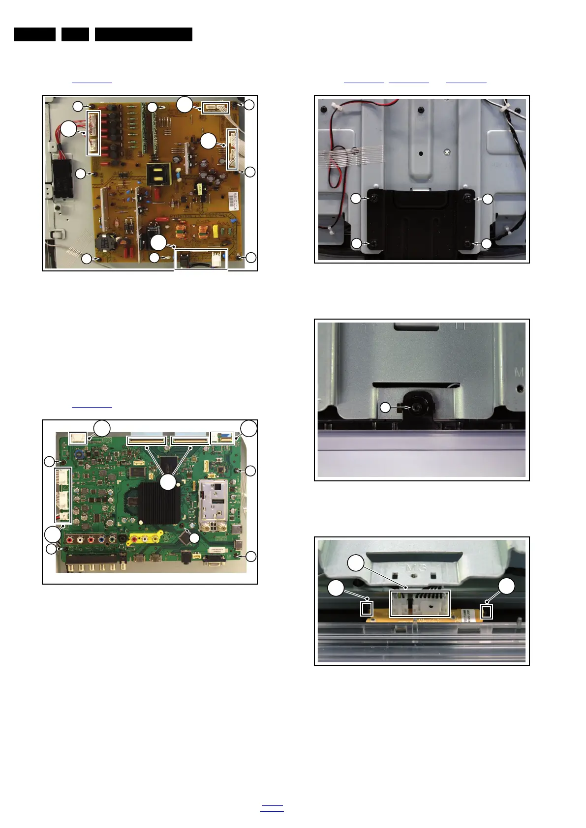
4.5.3 Main Power Supply
Refer to Figure 4-18
for details.
Figure 4-18 Main Power Supply
1. Unplug all connectors [1].
2. Remove the fixation screws [2].
3. Take the board out.
When defective, replace the whole unit.
Be aware to (re)place the spacers [3].
4.5.4 Small Signal Board (SSB)
Refer to Figure 4-19
for details.
Figure 4-19 SSB
1. Unplug all connectors [1] and [2].
2. Remove the fixation screws [3].
3. Take the board out.
When defective, replace the whole unit.
4.5.5 Mains Switch
The mains switch assy is mounted below the PSU on the front
bezel with two screws.
When replacing the switch, remove it from its bracket.
4.5.6 IR & LED Board
Refer to Figure 4-20
, Figure 4-21 and Figure 4-22 for details.
Figure 4-20 IR & LED Board -1-
Figure 4-21 IR & LED Board -2-
Figure 4-22 IR & LED Board -3-
1. Remove the stand [1].
2. Remove the IR & LED board cover [2].
3. Release the clips [3] that secure the IR & LED board.
4. Remove the connectors [4] on the IR/LED board.
18970_103_100323.eps
100323
1
2
2
2
2
2
2
1
3
3
1
1
18970_104_100323.eps
100323
2
2
1
3
3
3
3
3
2
18770_142_100215.eps
100215
1
1
1
1
18770_143_100215.eps
100215
2
18770_144_100215.eps
100215
4
3
3