Circuit Descriptions
EN 29TPS10.1A LA 7.
2013-Jul-05
back to
div. table
7.3 DC/DC Converters
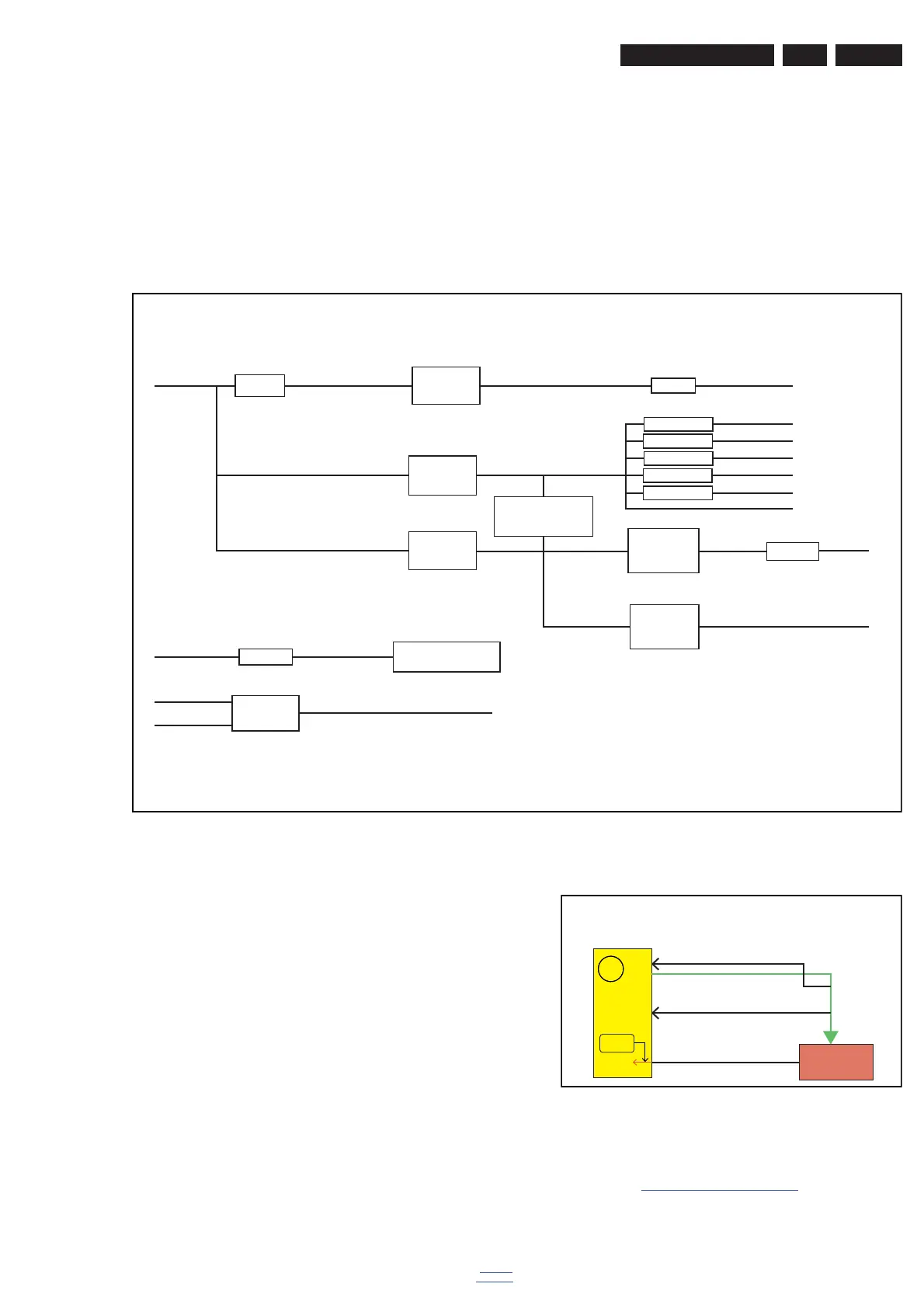
The on-board DC/DC converters deliver the following voltages
(depending on set execution):
• +5V-STANDBY, permanent voltage for the Stand-by
controller, LED/IR receiver and controls
• +3V3-STANDBY, power supply for LED/IR receiver and
controls
• +12V, input from the power supply for the panel common
(active mode); connector CN403 pins 28, 29, 30.
• +24V, input from the power supply for audio amplifier;
connector CN9902 pins 5 and 6.
• +1V2, from the power supply for the scaler IC MST6931.
• +1V8, supply voltage for DDR2 (diagram B03B)
• +3V3, general supply voltage
• +3.3V-TUN, supply voltage for tuner
• +5V, supply voltage for Headphone AMP
• +5V-USB, input intermediate supply voltage for USB
• +3V3 from the power supply for the scaler IC MST6931
Figures gives a graphical representation of the DC/DC
converters with its current consumptions:
Figure 7-4 DC/DC converters
7.4 Front-End Analogue ATV reception
7.4.1 Front-End Analogue
The Front-End for the analogue tuner consist of the following
key components:
• TUNER China DT21WN-2-E
• SCALER MST6931XP-Z1-VB EPLQFP-128
Below find a block diagram of the front-end application for
analogue.
Figure 7-5 Front-End analogue block diagram
7.5 HDMI
Refer to figure 7-6 HDMI input configuration for the application.
19450_203_130128.eps
130129
FB701
+5V_Standby
+3.3V_Standby
+1.2V_VDDC
+5V_Standby
PANEL_VCC
+5V_Normal
FB701
PVDD
P12V
P24V
FB401
VDDC
VDD33
AVDD ADC
AU33
FOR SPI Flash
AVDD DDR
USB_5V
+1.8V_DDR
AVDD33 DEMOD
VDD33 DMPLL
FB408
FB403
FB404
FB405
FB406
FB407
PVD
VDD
U702
AZ1117D
U701
AP7323
U703
1084P-ADJ
Earphone
Pre-AMP
AMP TPA3110D
Q401
A04449
U704
APL3511
Q701
3401
MST6931
I
2
C
I
2
C
IF_AGC
IF
IF_AGC is no use
RF_AGC
RF_AGC
int.
Hi-Z
RF_AGC
DT21WN-2-E
SAWless with ATV mode
X
X
19450_204_130128.eps
130129






 To Next Page