Mechanical instructions
GB 23CDR779 4.
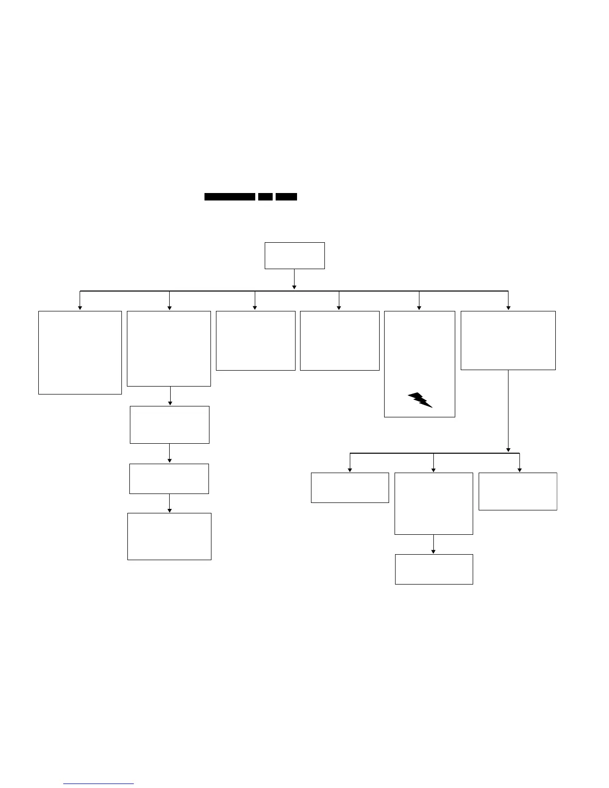
Dismantling 779
DISMANTLING INSTRUCTIONS CDR779
See exploded views for item numbers
assembling
↑
↓
disassembling
Cover 165
⇒
⇒
Remove 7 screws 166 → 172,
2 at each side and 3 at rear side.
Lift cover at rear side to remove.
CDR module includes :
Loader 81
CDR main board 1001
Loader bracket 82
⇒
Undo the 3 wire connections on the CDR
main board 1001.
⇒
Undo the 2 flex connections on CDR main board.
⇒ Remove 4 screws 90,91,93,94
(loader bracket 82 → frame 181).
⇒
Put the CDR player's rear side facing you.
Attention : flexes are not part of the CDR module
and have to stay with CDR player in case
of CDR module exchange !
Lift CDR module at rear side to remove.
⇒
On/Off & Stby LED board 1002
⇒
Undo the 2 wire connections on board.
⇒ Remove 2 screws 33 and 34
(on/off switch
→ front assy 1).
Remove power button 9 from on/off switch.
⇒
Front assy 1
Remove 2 screws 182, 183
(front assy 1
→ frame 181).
⇒
⇒
Unlock front assy from frame by releasing 7 snaps :
start with 2 on the top and two on the sides
and end with 3 at the bottom.
After disassembly put in front of the set (service position).
⇒
Put the CDR player's front side facing you.
⇒
I/O board 1004 Power supply unit 1003
WARNING: POSSIBILITY OF HIGH
VOLTAGE (300V) ON HEAT SINK,
EVEN AFTER REMOUNTING OF
PCB. DISCHARGE ELCAP 2121.
⇒
Put the CDR player's rear side facing you.
⇒ Remove screw 205
(mains connector → back plate 266).
⇒
Undo the 2 wire connections on PSU.
⇒
Remove 3 screws 189 → 191
(PSU board → frame 181).
⇒
Unlock snap on spacer 186.
⇒
Remove PSU.
⇒
⇒
Undo flex connection to CDR main board 1001.
⇒
Remove 3 screws 200 → 202, connecting
the 3 I/O sockets to back plate 266.
⇒
Remove board.
Put CDR player's rear side facing you.
Attention : flex is not part of the I/O board
and has to stay with CDR player in case
of I/O board exchange !
Remove 2 screws 31, 32
(ground wires
→ frame 181).
⇒
Display board 1002
⇒
Remove easy jog knob 51 pulling it forward.
Remove 11 screws 19
→ 29
(display board → front assy 1).
⇒
⇒
Undo the 3 wire connections on display board.
⇒
Release 2 snaps (1 on left and 1 on right side)
⇒
Remove display board.
Headphone board 1002
⇒
Pull board out of front assy 1.
Slide board out of middle key assy 3.
⇒
⇒
Undo wire connection on board.
⇒
Remove board.
⇒
Remove board.
CD module includes :
Loader 131
CD main board 1005
Loader bracket 132
⇒
Undo the 2 flex connections on CD main board.
⇒ Remove 4 screws 140 → 143
(loader bracket 132 → frame 181).
⇒
Put the CDR player's rear side facing you.
Attention : flexes are not part of the CD module
and have to stay with CDR player in case
of CD module exchange !
Lift CD module at rear side to remove.
⇒
CD out board 1002
⇒
⇒
Undo flex connection to CD main board 1005.
⇒ Remove 2 screws 209, 210 connecting
the 2 I/O sockets to back plate 266.
⇒
Remove board.
Put CDR player's rear side facing you.
Attention : flex is not part of the CD out board
and has to stay with CDR player in case
of CD out board exchange !
IR board 1002
⇒
Remove 2 screws 36 and 37
(IR board
→ front assy 1).
⇒
Undo wire connection on board.
⇒
Remove board.
Attention : when reassembling make sure
the wiring from display board to IR board is
positioned between FTD display and
middle key assy 3 !
CD main board 1005
⇒
Undo 2 flex and 2 wire connections
on CD main board.
⇒
Remove board.
⇒ Remove 4 screws 147 → 150
(CD main board → loader bracket 132).
CD loader assy 131
⇒
Remove loader.
⇒ Remove 4 screws 135 → 138
(CD loader → loader bracket 132).
CDM VAM1250
⇒
Open tray 43 by unlocking rack 16.
⇒ Unlock suspensions 35 → 38 from sub chassis 40.
⇒ Remove CDM VAM1250.
⇒
Remove clamper assy 45 by releasing 4 snaps
(2 on left 2 on right side) on chassis assy 1.
Undo wires of CDM VAM1250 from
wire retainers on sub chassis 40.
⇒
CL 06532151_016.eps
241100