10 EN
ISO male
connectors
Connect to
g White-edged blue
strip
Amplier relay
control lead
h Black strip Ground
i Yellow strip To the +12V car
battery which is
energized at all
times
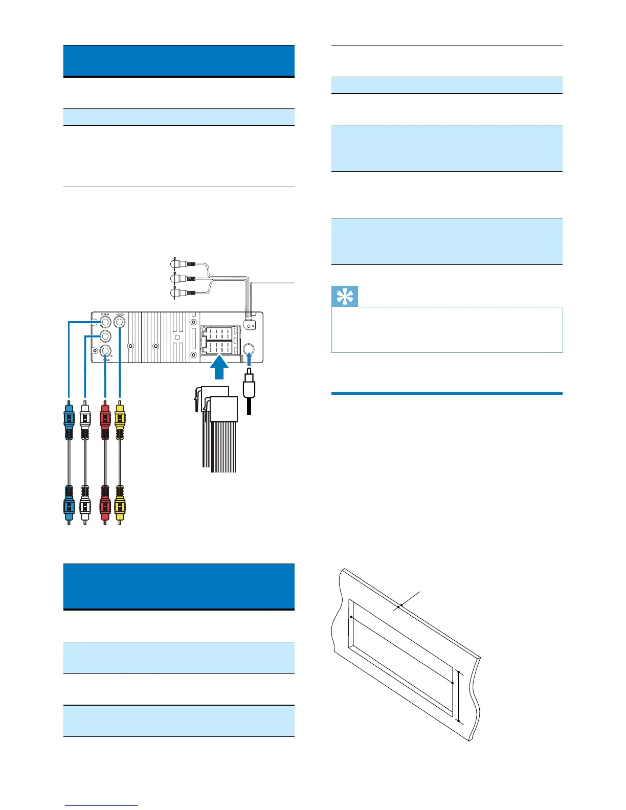
2 Connect the ISO male connectors and
other wires to the rear panel of the main
unit if necessary.
Sockets or
connectors on rear
panel
External sockets or
connectors
1 SUB-W
(Blue socket)
As indicated above
2 REAR L
(White socket)
Rear left speaker
3 REAR R
(Red socket)
Rear right speaker
4 VIDEO
(Yellow socket)
Video input socket
of external screen
L
ab cd
e
f
g
i
h
j
5 Sockets for ISO
male connectors
As indicated in step
1 above
6 Antenna socket Radio antenna
7 OE REMOTE
(Purple strip)
OE remote
8 VIDEO IN
(Yellow connector)
Video output socket
of an external video
player
9 AUDIO IN L
(White connector)
Left audio channel
output socket of an
external video player
10 AUDIO IN R
(Red connector)
Right audio channel
output socket of an
external video player
Tip
•
The pin arrangement for the ISO connectors depends
on the type of your vehicle. To avoid damage to the
unit, connect properly.
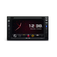
Mount into the dashboard
• If the car does not have an on-board drive
or navigation computer, disconnect the
negative terminal of the car battery.
• If the car battery is not disconnected, to
avoid short-circuit, make sure that the bare
wires do not touch each other.
1 Make sure that the car dashboard opening
is within these measurements.