Cabinet Disassembly Instructions
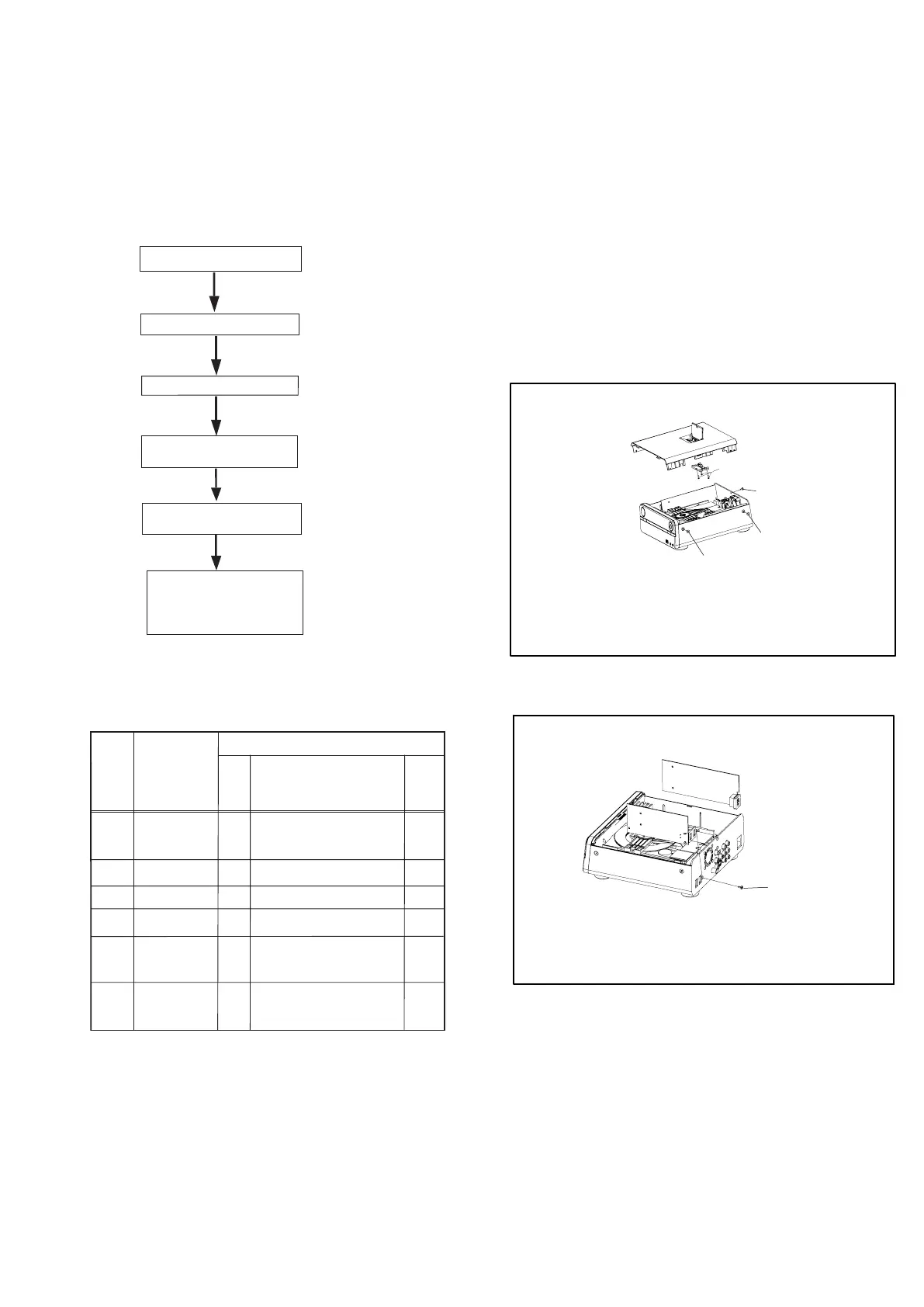
1. Disassembly Flowchart
This flowchart indicates the disassembly steps to gain
access to item(s) to be serviced. When reassembling,
follow the steps in reverse order. Bend, route, and
dress the cables as they were originally.
2. Disassembly Method
Note:
(1) Identification (location) No. of parts in the figures
(2) Name of the part
(3) Figure Number for reference
(4) Identification of parts to be removed, unhooked,
unlocked, released, unplugged, unclamped, or
desoldered.
0x = Screw, CNxx/Jxx/CONxx = Connector
D3.5X12BA is specification of screw.
* = Unhook, Unlock, Release, Unplu
g, or Desolder
e.g. 7(01) = seven Screws
ID/
Loc.
No.
Part
Removal
Fig.
No.
Remove/*Unhook/
Unlock/Release/
Unplug/Desolder
Note
[1]
[2]
[3]
[4]
[5]
[6]
2(A02) D3x6KB
1(A03) D3x10FA
3(A04) D2x8BT
2(A01) D3x8KM
1(A05) D3x10FT
4(A08) D3x6PWTT
5(A05) D3x10FA
4(A07) D3x15FM
3(A04) D2x8BT
4(A04) D2x8BT
5(A09) D3x8PA
D1
D2
D3
D4
D5
D6
PCB Bracket
4(A06) D3x10PWA
Clump Weight
DVD Door
8-1
[1] Top Cover
[2] PCB Bracket
[3] DVD Loader Driver
[4] Decoder Board
Fan
[5] Clump Weight
DVD Door
[6] Front Cabinet
Display Board
Bottom Board
Front Cabinet
Display Board
Bottom Board
Fig.D1
Fig.D2
A05
A03
A04
A02
A01
Top Cover
DVD Loader Driver
Decoder Board
Fan