40 10 July 2000 Diamond Line Amplifiers
Controls and Connectors
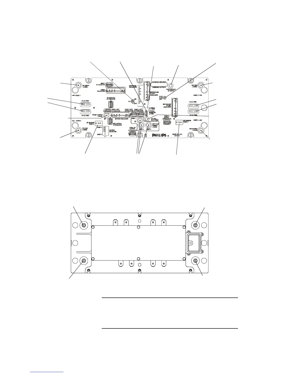
Figure 12. Diamond Line 2 Amp, Controls & Connectors
This illustration shows the Diamond Line2 amplifier module’s
controls and points of connection. Callouts are defined in the
following table. For locations of plug-in circuits, see page42.
4. Input Test
Point,TP1
5. Output Test
Point,TP3
5. Output Test
Point,TP2
5. Output Test
Point,TP4
7. Return Output
TestPoint
6. Return Input
TestPoints
(forports 2, 3, & 4)
8. +24 VDC
TestPoint
9. Fuses:
F1
F3
10. ALSC
On/Off Switch
11. ALSC
Gain Control
12. EMS & Power
Connector
14. Location for
Port 3 RF Sensor
(DD-EMS Kit)
15. EMS Module
RFInput
Connector
14. Location for
Port 4 RF Sensor
(DD-EMS Kit)
9. Fuses:
F2
F4
1. Forward Input/
ReturnOutput Jack, J1
2. Main Output/
ReturnInput Jack,J2
3. Secondary Output/
ReturnInput Jack,J4
3. Secondary Output/
ReturnInput Jack,J3
13. Location for
EMS Current
Sensor



 To Next Page