Diagnostic software
EN 18 S/SD/HD 3.1 PDP5.
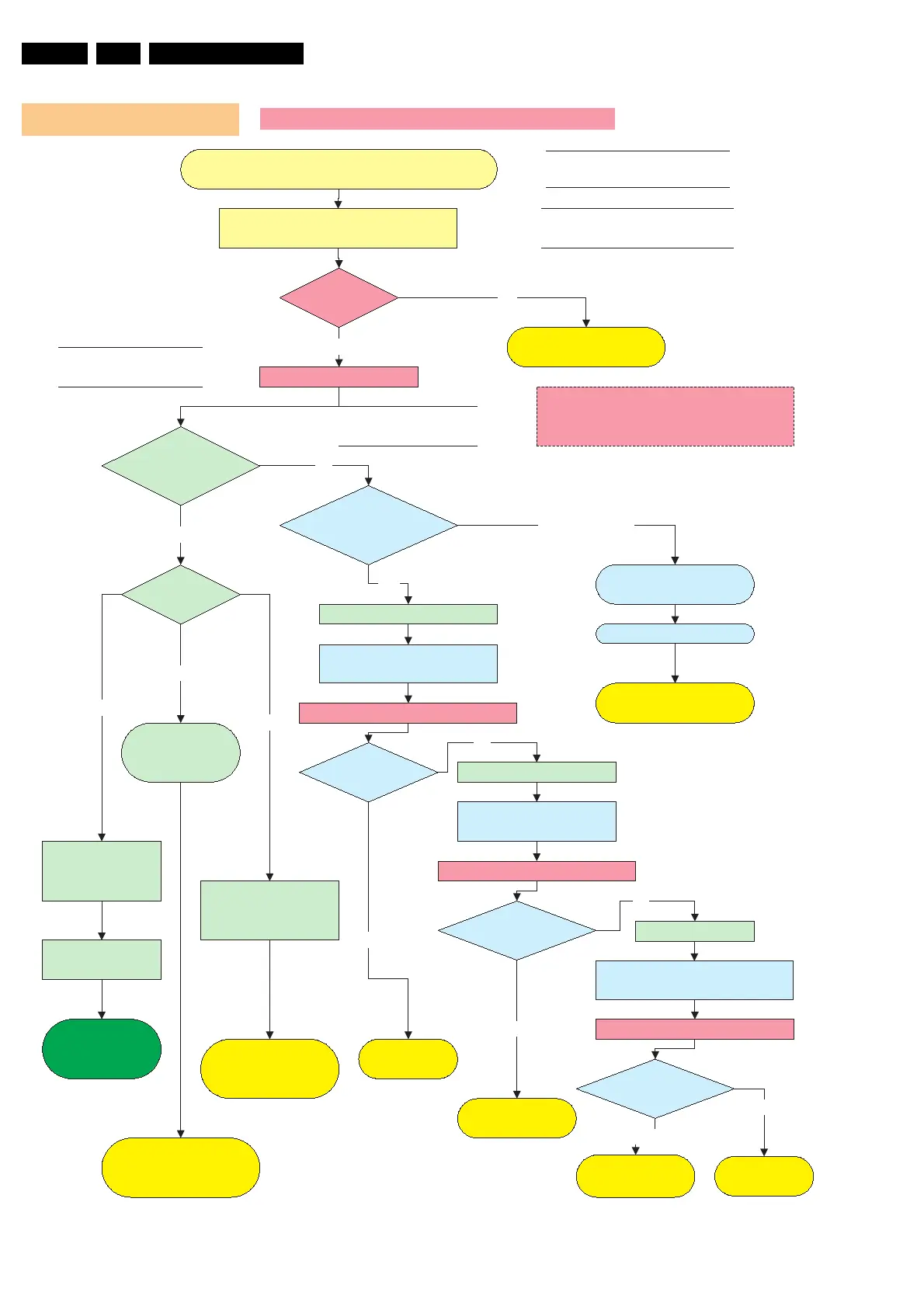
Figure 5-5
Operating voltages don´t exist V2 Versions
LED8003
Stby is on?
Green LED´s
8001, 8002
are on?
Connect set to mains.
Switch on On/Off switch (vacation switch)
Check SMPS outputs
Vs, Va, Vset, Ve, Vsc
see Sticker
Ye s
NO
Check CN8004 / 2pin
connector 220V AC
Check F8002
Fuse 250V/8A
On/Off relay
RLY8001/8002 acts?
Switch on via 1 or 2
Check Protection Red
LED8004
No Voltage output
Ye s
No
Disconnect VA Logic Buffer
CN8010 / CN8011
Disconnect X-main CN8007
Power Supply Check for 42SDV2
SMPS shutsdown?
Red LED8004 is on.
Protection
Reconnect mains. Switch on via 1 or 2
Stanby supply is defective.
Replace PSU
Ye s
Call SAM
or SDM
Disconnect mains cord
Disconnect Y-main CN8008
SMPS is working? Disconnect mains cord
No
Disconnect mains
Reconnect mains. Switch on via 1 or 2
SMPS is
working?
No
Replace
Y-Main board
Replace
X-Main board
SMPS is
working?
No
Replace defective
Logic Buffer board
Ye s
Reconnect mains. Switch on via 1 or 2
Replace PSU
Ye s
Check Stanby Line pin 11
on CN8002 must be low.
Go to repair scenario
as stand-alone
LED on Logic
main board ?
Data communication
from Philips
application to Logic
mains is OK.
Blinking
Continous on, means no
data communication over
LVDS Cable.
Green LED 8001,
8002
& Red LED are off
Ye s
No switch on of PSU
Switch from standby to on;
1 Via RC when Philips application is in.
2 Via Switch on Jig connector when Philips
application is removed
Discharge capacitors on Power supply, before
reconnecting X, Y or Logic Buffer board, use
2K4/10W discharge resistor
Go to repair scenario
as stand-alone
On
Check Power supply
on Logic-Main board.
3,3V and 5V
If Power supply on Logic
mains is not OK, change PSU
or Logic main board
Off