Preparations
Rear Connections
The type plate is located at the rear of the
system.
A
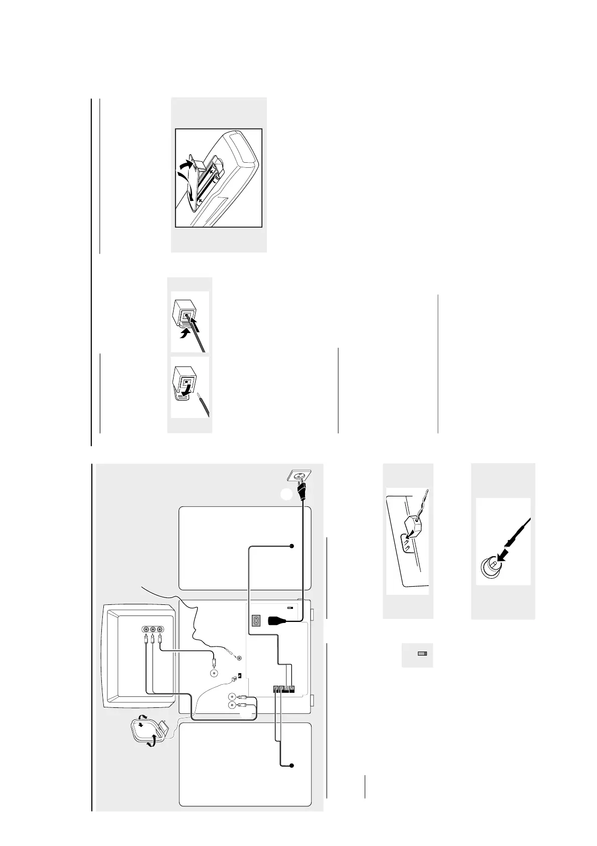
Power
Before connecting the AC power cord to the
wall outlet, ensure that the following are done;
-If your system is equipped with a
Voltage Selector, set the VOLTAGE
SELECTOR to the local power line
voltage.
- All other connections have been made.
WARNING!
-For optimal performance, use only the
original power cable.
-Never ma ke or change any connections
with the power switched on.
To avoid overheating of the system, a safety
circuit has been built in. Therefore, your
system may switch to Standby mode
automatically under extreme conditions
.
If
this happens, let the system cool down
before reusing it (not available for all versions).
B
Antennas Connection
Connect the supplied AM loop antenna and FM
antenna to the respective terminals. Adjust the
position of the antenna for optimal reception.
AM Antenna
Position the antenna as far as possible from a TV,
VCR or other radiation source.
FM Antenna
For better FM stereo reception, connect an
outdoor FM antenna to the FM ANTENNA
terminal.
SPEAKERS 6Ω
R
+
ñ
L
ñ
+
SUBWOOFER
OUT
AUX/
CDR
IN
AM ANTENNA
AC
MAINS
speaker
(right)
speaker
(left)
AC power cord
FM wire
antenna
A
B
C
FM ANTENNA
VOLTAGE
SELECTOR
110V-
127V
220V-
240V
VIDEO
IN
Television
L
R
AUDIO
OUT
AM loop
antenna
VIDEO OUT
(CVBS)
D
E
VOLTAGE
SELECTOR
110V-
127V
220V-
240V
Preparations
C
Speakers Connection
Front Speakers
Connect the speaker wires to the SPEAKERS
(FRONT) terminals, right speaker to "R" and left
speaker to "L", coloured (marked) wire to "+"
and black (unmarked) wire to "-".
1
2
Fully insert the stripped portion of the speaker
wire into the terminal as shown.
Notes:
–For optimal sound performance, use the
supplied speakers.
– Do not connect more than one speaker to any
one pair of
+
/
-
speaker terminals.
– Do not connect speakers with an impedance
lower than the speakers supplied. Please refer to
the SPECIFICATIONS section of this manual.
D
Video Out Connection
Connect the VIDEO OUT (CVBS) terminal
at the rear of the system to the TV or VCR
VIDEO IN for viewing or recording.
Note:
–To avoid magnetic interference with the picture
on your TV, do not position the front speakers too
close to the TV.
E
Connecting other equipment to your
system
Connect the audio left and right OUT terminals
of a TV, VCR, Laser Disc player, DVD player or
CD Recorder to the AUX/CDR IN terminals.
Note:
–If you ar e connecting equipment with a mono
output (a single audio out terminal), connect it to
the AUX/CDR IN left terminal. Alternatively, you
can use a "single to double" cinch cable (still be
mono sound).
Inserting batteries into the
Remote Control
Insert two batteries (Type R06 or AA) into the
remote control with the correct polarity as
indicated by the + and - symbols inside the
battery compartment.
CAUTION!
– Remove batteries if they are exhausted
or not to be used for a long time..
– Do not use old and new or different
types of batteries in combination.
– Batteries contain chemical substances, so
they should be disposed off properly.