Do you have a question about the Philips HTS3300/98 and is the answer not in the manual?
Details mains voltage, mains frequency, power consumption, and unit dimensions.
Details radio tuner performance including tuning range, selectivity, and distortion.
Covers audio output power, frequency response, hum, and residual noise levels.
Details media playback features like video decoding, DAC, and signal system.
Illustrates measurement setups for Tuner FM, Tuner AM, CD, and Recorder.
Warns about electrostatic discharge and provides guidelines for safe handling.
Details procedures and requirements for using lead-free solder.
Step-by-step guide to remove the DVD loader assembly from the unit.
Instructions for removing Tuner, Mono, Front, and PSU modules.
Visual guide showing the positions of major boards within the set.
Describes how to perform display tests using different patterns.
Details EEPROM format, rotary encoder, and service test program exit functions.
Guides on upgrading the DVD version matrix and firmware.
Explains how to activate and deactivate trade mode for dealer control.
Procedure to change the tuning grid settings for the tuner.
Shows the pin connections and mapping for the FTD display segments.
High-level overview of the unit's functional blocks and interconnections.
Illustrates the internal wiring connections between various modules.
Circuit and layout for front display, standby, and MIC input.
Detailed circuit diagrams for the main mono board, broken into sections.
PWB layout diagrams for the mono board, showing component placement.
Circuit diagram for the power supply unit.
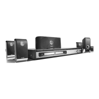
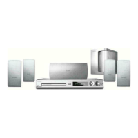
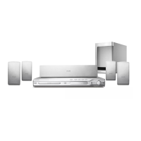
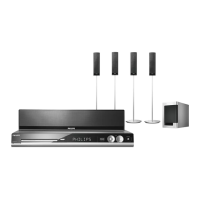
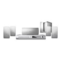
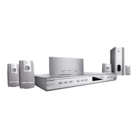
Visual representation of the unit's components and their assembly.
Details a replacement of a schematic diagram in a previous manual version.
Details a revision to the spare part list for specific HTS3300 models.