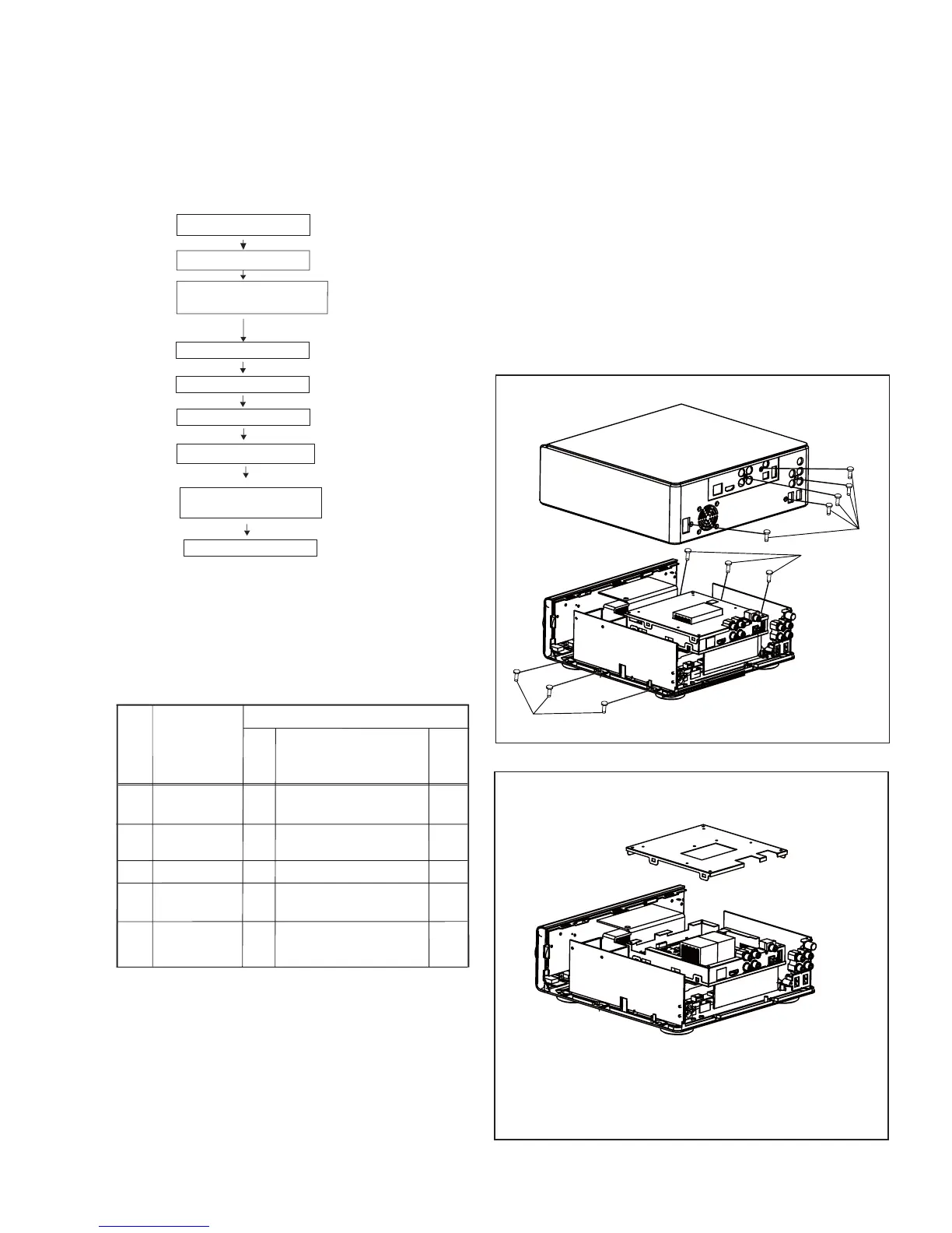
Cabinet Disassembly Instructions
1. Disassembly Flowchart
This flowchart indicates the disassembly steps to gain
access to item(s) to be serviced. When reassembling,
follow the steps in reverse order. Bend, route, and
dress the cables as they were originally.
2. Disassembly Method
Note:
(1) Identification (location) No. of parts in the figures
(2) Name of the part
(3) Figure Number for reference
(4) Identification of parts to be removed, unhooked,
unlocked, released, unplugged, unclamped, or
desoldered.
0x = Screw, CNxx/Jxx/CONxx = Connector
D3.5X12BA is specification of screw.
* = Unhook, Unlock, Release, Unplug, or Desolder
e.g. 7(01) = seven Screws
ID/
Loc.
No.
Part
Removal
Fig.
No.
Remove/*Unhook/
Unlock/Release/
Unplug/Desolder
Note
[4] EARTHING PLATE
[3] MPAEG BOAARD&
MPEG MID\BOTTOM COVER
MPAEG BOARD
&MPEG MID\
BOTTOM COVER
[2] MPEG TOP COVER
[1]
[2]
[3]
[4]
[5]
5(A01) D3x10FA
6(A02) D3x8FT
4(A03) D3x8BTH,
3(A05) D3x8FT
8 (A06) D3x8PA
D1
D3
D5
D8
D9
Fig. D1
Fig. D2
[1] TOP COVER
TOP COVER
[5] POWER BOARD
POWER BOARD
[6] AMP+MUC BOARD
[7] DVD DOOR
[8]VOLUME KNOB COVER,
FRONT PANEL
VOLUME KNOB
COVER,FRONT
PANEL
[9] VFD DISPLAY PCB
VFD DISPLAY PCB
1(A04) D3x6FMTT
A01
A02
A02
8-1