Do you have a question about the Philips MBD3000/93 and is the answer not in the manual?
Identifies the physical location of key PCBs within the unit.
Provides general specifications like power supply, consumption, and radio tuning range.
Details radio tuning range, signal-to-noise ratio, and selectivity.
Lists audio performance metrics and video output specifications.
Specifies the physical dimensions and net weight of the main unit and speakers.
Details laser power output and wavelength for BD, DVD, and CD.
Outlines supported media formats and compression types for video, audio, and pictures.
Covers risks of electric shock, fire, injury, and overheating.
Guidelines for product maintenance and avoiding contamination.
Instructions on proper disposal of the product and batteries according to regulations.
Steps to access and read the complete user manual from the provided CD.
Verifies specified clearance distances between terminals and metallic parts after repair.
Measures leakage current between earth ground and exposed parts to ensure safety.
General safety rules for repair, including transformer use and cable routing.
Critical warnings about ESD, live voltage sections, and module replacement.
Specific safety rules for handling the laser device, emphasizing eye protection.
Explains how to identify pins on ICs and connectors.
Guides on connecting/disconnecting FFC cables safely.
Information and requirements for using lead-free solder.
Procedures for removing and installing flat pack integrated circuits.
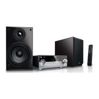
Identifies main unit controls and functions.
Explains functions of buttons on the remote control.
Guides on connecting speakers, video, and audio cables.
Instructions for routing audio from external sources.
Steps for connecting and accessing USB storage devices.
Information on connecting to the internet for updates and BD Live.
Guidance on connecting the FM antenna for reception.
Safety precautions and steps for connecting the AC power cable.
Visual flowchart indicating the sequence for accessing internal components.
Details the specific parts and screws to remove for disassembly.
Step-by-step guide for downloading and installing software updates.
Instructions on how to check the current software version installed on the unit.
Circuit and layout diagram for the USB interface board.
Circuit and layout diagram for the headphone output board.
Electrical schematic for the Amplifier and MCU board.
Physical layout of components on the Amplifier and MCU board.
Electrical schematic for the Vacuum Fluorescent Display board.
Physical layout of components on the VFD Display board.
Electrical schematic for the Decoder board, part 1.
Electrical schematic for the Decoder board, part 2.
Electrical schematic for the Decoder board, part 3.
Electrical schematic for the Decoder board, part 4.
Electrical schematic for the Decoder board, part 5.
Electrical schematic for the Decoder board, part 6.
Electrical schematic for the Decoder board, part 7.
Electrical schematic for the Decoder board, part 8.
Electrical schematic for the Decoder board, part 9.
Electrical schematic for the Decoder board, part 10.
Electrical schematic for the Decoder board, part 11.
Electrical schematic for the Decoder board, part 12.
Physical layout of components on the Decoder board.
Electrical schematic for the Power Supply board.
Physical layout of components on the Power Supply board.
| Internet Connectivity | Yes |
|---|---|
| BD-Live | Yes |
| Ethernet | Yes |
| USB | Yes |
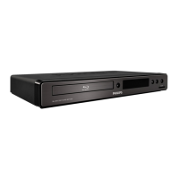
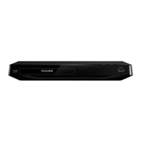
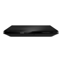
| Type | Blu-ray Player |
| Video Output | HDMI, Composite |
| Audio Output | Optical Digital |
| Playback Formats | CD, DVD |
| Video Upconversion | 1080p |
| Disc Types | BD-R/RE, DVD±R/RW, CD-R/RW |
| Resolution | 1920 x 1080 |