EasyManua.ls Logo

Philips MCD728 User Manual

Philips MCD728
41 pages
To Next Page IconTo Next Page
Page #1 background imageLoading...
Page #1 background image
Version 1.2
MCD728
© 3141 785 31692
Service Manual
DVD Micro System
all versions
Published by DB 0730 Service Audio Printed in The Netherlands Subject to modification
©
Copyright 2007 Philips Consumer Electronics B.V. Eindhoven, The Netherlands
All rights reserved. No part of this publication may be reproduced, stored in a retrieval
system or transmitted, in any form or by any means, electronic, mechanical, photocopying,
or otherwise without the prior permission of Philips.
Handling chip components ............................................................1-1
Information about lead-free soldering............................................1-2
Technical specification...................................................................2-1
Service tools..................................................................................2-1
Service measurement setup..........................................................2-2
Connections and controls......................................................3-1...3-4
Disassembly diagram............................................................4-1...4-2
Software version and upgrading....................................................5-1
Set block diagram..........................................................................5-2
Set wiring diagram.........................................................................5-3
VFD BOARD
circuit diagram ..........................................................................6-1
layout diagram ..........................................................................6-2
TUNER BOARD
circuit diagram
......................................................................7-1
layout diagram .......................................................................7-2
AMP BOARD
circuit diagram ..........................................................................8-1
layout diagram ..........................................................................8-2
CPU BOARD
circuit diagram ..........................................................................9-1
layout diagram ..........................................................................9-2
Pre-AMP BOARD
circuit diagram ........................................................................10-1
layout diagram ........................................................................10-2
DVD MPEG BOARD
circuit diagram ..............................................................13-1...13-5
layout diagram ........................................................................13-6
Exploded view diagram......................................................14-1...14-2
Service partslist.................................................................14-3...14-5
Factory partslist..................................................................15-1...15-5
TABLE OF CONTENTS
CLASS 1
LASER PRODUCT

Other manuals for Philips MCD728

Question and Answer IconNeed help?

Do you have a question about the Philips MCD728 and is the answer not in the manual?

Philips MCD728 Specifications

Picture/Display IconPicture/Display
D/A converter12bit, 108MHz
Picture enhancementHigh Def (720p, 1080i), Video upsampling, Video upscaling
Sound IconSound
Output PowerTotal 400W RMS
Sound EnhancementClass 'D' Digital Amplifier, Digital Sound Control 4 modes, Dynamic Bass Boost, Loudness, Moving Speakers
Sound SystemDolby Virtual speaker, Dolby Digital
Loudspeakers IconLoudspeakers
Main SpeakerSpeaker grilles detachable, 3x3" bullet full range
Subwoofer driver8" woofer
Subwoofer typePassive
Power IconPower
Power supply110-240V, 50/60 Hz
Dimensions IconDimensions
Main speaker dimensions (W x H x D)150 x 323 x 150 mm
Set dimensions (W x H x D)240 x 160 x 230 mm
Subwoofer dimensions (W x H x D)430 x 262 x 292 mm
Packaging dimensions (W x H x D)740 x 496 x 354 mm
Weight incl. Packaging20 kg

Summary

DVD Micro System Service Manual MCD728

Handling Chip Components

Safety Precautions and Warnings

Important safety information regarding ESD, laser radiation, and general handling.

Lead-Free Soldering and Service Instructions

Lead-Free Soldering Identification and Procedures

Details on identifying and performing lead-free soldering, including tool requirements.

Service Instructions and Safety Requirements

Guidelines for returning the set to original condition and essential safety checks post-repair.

Technical Specifications and Service Equipment

System, DVD, Amplifier, and Tuner Specifications

Detailed technical data for the system, DVD, amplifier, and tuner components.

Service Measurement Procedures

Tuner Measurement Setup

Procedures for measuring tuner performance using specific test equipment.

Connection and Control Setup

Speaker and Subwoofer Connection

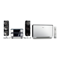
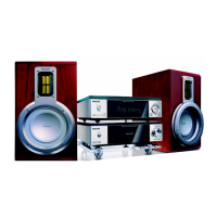
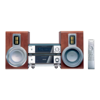
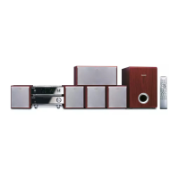
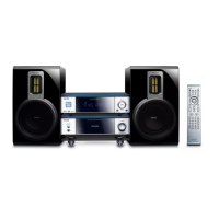
Guidelines for positioning speakers and connecting them, including subwoofer.

External Device Connectivity

System Connections and Operations

Functional Overview

Remote Control Functions

Detailed explanation of buttons and their functions on the remote control.

System Unit Controls

Overview of buttons and the display on the main DVD system unit.

Detailed Functional Overview

DVD Part Disassembly Diagram

DVD Part Disassembly Steps

Steps for removing the bottom cover, back panel, and DVD mechanism.

Amplifier Part Disassembly Diagram

Amplifier Part Disassembly Steps

Steps for removing the bottom cover, back panel, and amplifier boards.

Software Version and Upgrading

Inspecting Software Version

Steps to check the current software version of the system.

Software Upgrade Process

Instructions for upgrading the system's software using an upgrade disk.

System Block Diagram

Overall System Architecture

Visual representation of how different blocks of the system are interconnected.

Set Wiring Diagram

Inter-Board Connections

Diagram showing how the various PCBs are wired together.

DVD MPEG Board Circuit Diagram - Part 1

Main MPEG Processor and HDMI Circuitry

Schematic of the MPEG board focusing on the main processor and HDMI interface.

DVD MPEG Board Circuit Diagram - Part 2

Video Output and Audio Circuitry

Details of video output circuits (YUV, CVBS) and audio processing on the MPEG board.

DVD MPEG Board Circuit Diagram - Part 3

DVD MPEG Board Circuit Diagram - Part 4

DVD Exploded View Diagram

Amplifier Exploded View Diagram

Factory BOM - Part 1

Factory BOM - Part 2

Factory BOM - Part 3

Factory BOM - Part 4

Factory BOM - Part 5

Related product manuals