EasyManua.ls Logo

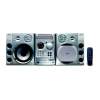
Philips MCM595 User Manual

Philips MCM595
58 pages
To Next Page IconTo Next Page
Page #1 background imageLoading...
Page #1 background image
CLASS 1
LASER PRODUCT
COMPACT
DIGITAL AUDIO
Service
Service
Service
Service
Service
MCM595/21
Impresso no Brasil Sujeito a Alterações Todos os Direitos Reservados
Micro System
4806 725 27190
Dez/2005
Service Manual
Conteúdo P á gina
Localização dos Painéis e Variação de Versões...............................2
Especifi cações Técnicas......................................................................3
Manuseando componentes SMD. ..................................................4
Ajustes....................................................................................5
Instruções de Segurança........................................................6
Instruções de Desmontagem e Posições de Serviço........................7
Programa de Testes.............................................................10
Diagrama em Bloco..................................................................11
Diagrama de Conexões..........................................................12
Painel de Controle Frontal..........................................................13
Painel Tuner ECO6 : Sistemas Não-Cenelec....................................20
Agente de Áudio USB.........................................................................23
Módulo 5DTC.........................................................................................25
Diagrama em Blocos 5DTC.................................................................33
Painel CD 5DTC..................................................................34
Layout Componentes e Cobre......................................................35
Painel Controle 5DTC.............................................................37
Painel MP3............................................................................................38
Layout componentes e Cobre...............................................................39
Vista Explodida Mecânica...................................................40
Módulo Power 2003.........................................................41
Painel Combi ....................................................................47
Painel Rede....................................................................55
Vista Explodida Geral..................................................................58

Other manuals for Philips MCM595

Question and Answer IconNeed help?

Do you have a question about the Philips MCM595 and is the answer not in the manual?

Philips MCM595 Specifications

Sound IconSound
output power4000 watts PMPO
sound enhancementMAX Sound, Digital Sound Control 4 modes, Virtual Environment Control, Class "D" Digital Amplifier
Loudspeakers IconLoudspeakers
main speaker3 way, Bass Reflex Speaker System
woofer size6.5 inches
tweeter size2 inches
Audio Playback IconAudio Playback
playback mediaCD, CD-R, CD-RW, MP3-CD
number of discs5
pc link playback modeUSB connection
Tuner/Reception/Transmission IconTuner/Reception/Transmission
tuner bandsFM Stereo, MW
station presets40
tuner enhancementsAuto Store, Easy Set (Plug & Play)
Connectivity IconConnectivity
aux inLine in
pc linkUSB 2.0
headphone jack3.5 mm
Dimensions and Weight IconDimensions and Weight
set dimensions175 x 268 x 316 mm
main speaker dimensions240 x 268 x 222 mm
packaging dimensions547 x 374 x 455 mm
weight including packaging14.5 kg

Summary

Technical Specifications

SMD Component Handling and Safety

Service Safety Precautions

Essential safety measures for handling components and preventing ESD damage.

Shock and Fire Risk Test

Procedure for testing safety against electric shock and fire hazards after repair.

Adjustment Procedures

General Safety and Maintenance Instructions

BGA Rework and Service Precautions

Detailed steps and precautions for reworking Ball Grid Array components and general service.

Disassembly Instructions

5DTC Module Disassembly

Procedure for safely removing the 5DTC module from the main unit.

Service Test Program

Block Diagram

Connection Diagram

Front Panel Schematic Part 1

Front Panel Schematic Part 2

Front Panel Schematic Part 3

ECO6 Tuner Panel

ECO6 Tuner Schematic (Non-Cenelec)

Tuner Adjustment Table

USB Audio Agent

USB Audio Agent Schematic

Maintenance Tips and Troubleshooting

Eye-Pattern Signal Verification

Procedure for checking the eye-pattern signal using an oscilloscope for CD drive diagnostics.

CD Drive Replacement Warning

5DTC Module Connection Diagram

5DTC MP3 Version Block Diagram

MP3 Panel Schematic

Power Module 2003

Class D Amplifier Operation

Class D Block Diagram

Block diagram explaining the operation of the Class D amplifier, including its key stages.

Class D Amplifier Description

Combi Panel Power Module Schematic

Left Channel Amplifier

Details on the left channel amplifier's modulator, driver, and power FETs.

Right Channel Amplifier

Details on the right channel amplifier's modulator, driver, and power FETs.

Combi Panel Power Supply, Oscillator & Pre-Amplifier

Combi Panel Amplifier - Left Channel

Combi Panel Amplifier - Right Channel

Mains Panel Schematic Diagram

Related product manuals