Do you have a question about the Philips MCM277 and is the answer not in the manual?
Details component variations per board for MCM277 versions.
Lists feature differences across MCM277 versions.
General technical parameters of the system.
Technical details for FM and MW tuner sections.
Power output, frequency response, and DSC details.
Technical details for Compact Disc playback.
Technical details for MP3 and WMA CD playback.
Procedures and diagrams for measuring FM tuner performance.
Procedures and diagrams for measuring AM tuner performance.
Procedures and diagrams for measuring CD playback performance.
Important safety warnings, ESD precautions, and laser product classification.
Guidelines for handling lead-free soldering and identifying relevant sets.
Procedures for returning the set to original condition after repair.
Step-by-step guide for diagnosing CD playback issues.
Methods for verifying CD playback compatibility and performance.
Guidance for informing customers about CD-related checks and faults.
Step-by-step guide and precautions for cleaning the CD player lens.
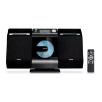
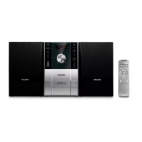
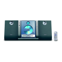
Instructions on how to use the remote control effectively.
Step-by-step guide for setting the system's clock.
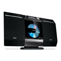
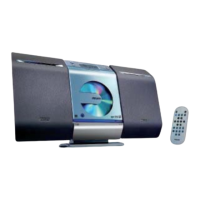
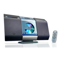
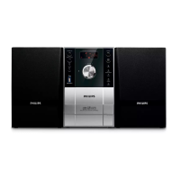
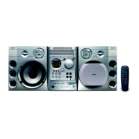
Description of buttons and functions directly on the Hi-Fi system unit.
Detailed explanation of each button on the remote control.
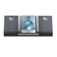
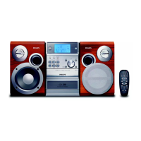
Instructions on how to position the MCM275 unit.
Information on connecting cables to the rear of the unit.
Details on connecting FM and AM antennas.
How to connect non-USB audio appliances to the system.
How to connect USB memory devices for music playback.
Instructions for connecting AC power and important safety warnings.
Solutions for common issues like non-responsive system, remote control, and clock settings.
Solutions for sound quality, sound output reversal, and poor radio reception.
Solutions for "NO DISC" errors and problems with USB file display.
Step-by-step guide to disassemble the rear section and PCBs.
Instructions for removing the display lens and volume knob.
Procedures for removing the CD module and door carrier assembly.
Procedures for performing key input tests and display element checks.
Functions for testing ADC inputs and clearing the EEPROM.
A visual representation of the main components and their interconnections.
A schematic showing the electrical connections between different boards and components.
Block diagram detailing the RDS/RBDS pre-processor circuit.
Detailed pin functions for the RDS/RBDS pre-processor IC.
Block diagram illustrating the power amplifier circuit.
Detailed pin functions for the TDA1517 power amplifier IC.
Block diagram of the TEA5757 self-tuned radio receiver.
Detailed pin functions for the TEA5757 radio receiver IC.
Detailed pin functions for the TEA5762 radio receiver IC.
Component layout diagram for the Main Board (5757) top view.
Component layout diagram for the Main Board (5757) bottom view.
Schematic diagram for the Main Board (5757).
Component layout diagram for the Main Board (5762) top view.
Component layout diagram for the Main Board (5762) bottom view.
Schematic diagram for the Main Board (5762).
Component layout diagram for the HP Jack Board top view.
Component layout diagram for the HP Jack Board bottom view.
Schematic diagram for the HP Jack Board.
List of electrical components for the Main Board.
Information about the CD & MCU Board, intended for orientation.
Component layout diagram for the CD&MCU Board top view.
Component layout diagram for the CD&MCU Board bottom view.
Schematic diagram for the CD portion of the CD&MCU Board.
Schematic diagram for the MCU portion of the CD&MCU Board.
Component layout diagram for the SW Board top view.
Component layout diagram for the SW Board bottom view.
List of electrical components for the CD & MCU Board.
Block diagram illustrating the LCD driver IC.
Detailed pin functions for the LCD driver IC.
Component layout diagram for the AC Power Board top view.
Component layout diagram for the AC Power Board bottom view.
Schematic diagram for the AC Power Board.
Component layout diagrams for the AC Socket Board (top and bottom).
Component layout diagrams for the Door Motor Board (top and bottom).
Component layout and schematic for the RC Board.
Component layout diagram for the Display Board top view.
Component layout diagram for the Display Board bottom view.
Schematic diagram for the Display Board.
Component layout diagram for the Key Board top view.
Component layout diagram for the Key Board bottom view.
Schematic diagram for the Key Board.
Component layout diagram for the SP & ANT Board top view.
Component layout diagram for the SP & ANT Board bottom view.
Schematic diagram for the SP & ANT Board.
An exploded view illustrating the mechanical assembly of the set.
List of mechanical and accessory parts for the main unit.
Comprehensive list of electrical components for various boards.
Component lists for several key PCBs including Main, Display/MCU, CD/USB, and Audio Processor.
Component lists for Key, AC Power, Speaker/Antenna, RC, and Tuner sections.
Procedure to check the system's software version via the front panel.
Method to erase all stored tuner program stations.
A visual representation of the main components and their interconnections.
A schematic showing the electrical connections between different boards and components.
Component layout for the Main Board, top side view.
Component layout for the Main Board, bottom side view.
Schematic diagram for the Main Board.
Component layout diagram for the CD & CD Door Motor & Limit Switch Board top view.
Component layout diagram for the CD & CD Door Motor & Limit Switch Board bottom view.
Schematic diagram for the CD & Limit SW Board.
Component layout diagrams for multiple boards (top view).
Component layout diagrams for multiple boards (bottom view).
Component layout diagram for the Key Board top view.
Component layout diagram for the Key Board bottom view.
Schematic diagram combining Key Board and AC Power Board circuits.
Schematic diagrams for HP Jack, SP & ANT, and RC boards.
A comprehensive exploded view of the mechanical components and assembly.
List of mechanical and accessory parts for the ALI solution.
List of electrical components for the ALI solution.
Component lists for Main, Key, and AC Power PCBs.
Summary of changes and updates made across different manual versions.
| output power | 2 x 5 W RMS, 2 x 10 W music power |
|---|---|
| sound enhancement | digital sound control 4 modes, Dynamic Bass Boost |
| speaker drivers | 4" woofer |
|---|---|
| speaker types | bass reflex speaker system |
| playback media | CD, CD-R, CD-RW, MP3-CD, WMA-CD |
|---|---|
| disc playback modes | repeat/shuffle/program |
| USB direct playback modes | fast backward/fast forward, play/pause, previous/next, program play, repeat, shuffle, stop |
| tuner bands | FM stereo, MW |
|---|---|
| RDS | program type, station name, radio text, RDS clock set |
| station presets | 40 |
| audio/video output | Headphone (3.5mm) |
|---|---|
| MP3 link | 3.5mm stereo line in |
| USB | USB host |
| power supply frequency | 50 Hz |
|---|---|
| power supply voltage | 220 - 240 V |
| eco power standby | 1 W |
| main speaker dimensions (W x D) | 160 x 90 mm |
|---|---|
| gross weight | 5.5 kg |
| main speaker height | 269 mm |