SECTION 3 TECHNICAL DESCRIPTION
3.1 GENERAL OVERVIEW
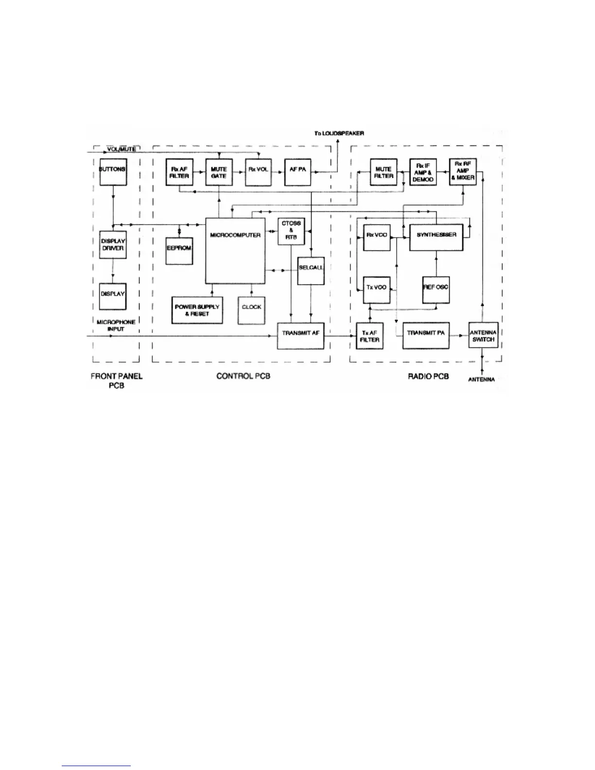
Shown in figure 3.1 is the overall simplified block diagram of the PRM80.
Figure 3.1 PRM80 - Overall Block Diagram
The transceiver consists of three printed circuit board assemblies.
i) Front Panel Board
Containing the liquid crystal display, its driving circuit, push button switches and
display backlighting.
ii) Control Board
Containing the microprocessor with its associated clock and latches, EEPROM
memory, power supply and reset circuit, transmitter audio processing, receiver
audio processing, selective call audio processing and CTCSS signalling option.
Section 3 Page 1