Mechanical Instructions
EN 24 SDI PDP4.
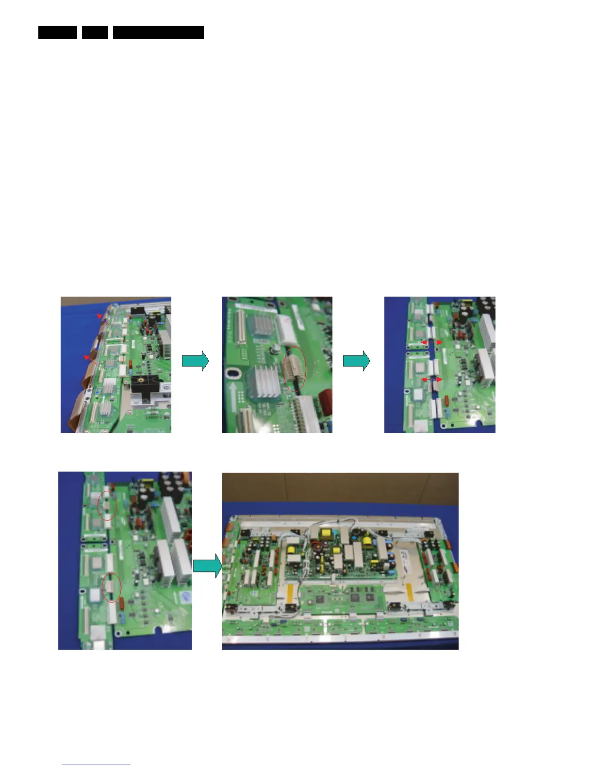
4.1.5 Exchange YBU, YBL and YM board
1. Separate all the FPC connector s of YBU (Y-Buffer upper)
and YBL (Y-Buffer lower). See “Photo 1”.
2. Separate all the connector of CN5001 and CN5008 from Y-
Main. See “Photo 2”.
3. Loosen all the screws of YBU, YBL, and YM. See “Photo
3”.
4. Remove the board from chassis.
5. Remove the connector of CN5006 and CN5007 among
YBU, YBL and YM.
6. Remove the YBL and YBU from Y-main.
7. Remove the defected board.
Note: When replacing the Logic board or Y-main board for
a lead-free (Pb-free) board, always replace them together.
(this is only valid for the 37” SD v4 displays!)
8. Re-assemble the YBU and YBL to the Y-Main.
9. Connect the connector of CN5006 and CN5007 among
YBU, YBL and YM. See “Photo 4”.
10. Arrange the board on the chassis and then screw to fix.
11. Connect the FPC and YM of panel to the connector. See
“Photo 5”.
12. Supply the electric power to the module and then check the
waveform of the board.
13. Turn “off” the power after the waveform is adjusted.
Figure 4-17 Photo 1, 2, and 3: Dis-assembly of YBU, YBL, and YM
Figure 4-18 Photo 4 and 5: Re-assembly of YBU, YBL, and YM