Alignments
EN 52 SDI PDP8.
8. Alignments
Index of this chapter:
8.1 Alignments 37” SD v4
8.2 Alignments 42” SD v2
8.3 Alignments 42” SD v3
8.4 Alignments 42” HD v3
8.6 Alignments 42” HD v4
8.7 Alignments 50” HD v3
8.8 Alignments 50” HD v4
8.9 Alignment value overview (all screens)
Important: Remove all non-default jumpers and reset all DIP
switches, after the repair!
8.1 Alignments 37” SD v4
1. Set the pattern to Full White (jumper CN2008 on the Logic
Board)
2. Set Vsch to -38V (see Figure “Waveform adjustment”).
Check with a digital multimeter, connected between the Y-
scan test point and ground. Adjust the voltage with
VR5000.
3. Check the waveform using an Oscilloscope.
• Triggering through V_TOGG of the LOGIC Board.
• Connect the “ODD” test point, located at the centre of
Y_buffer, to the other channel, and then check the first
SF (sub-frame) waveform of oneTV-Field.
• Check the waveform by adjusting Horizontal Division of
the oscilloscope.
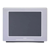
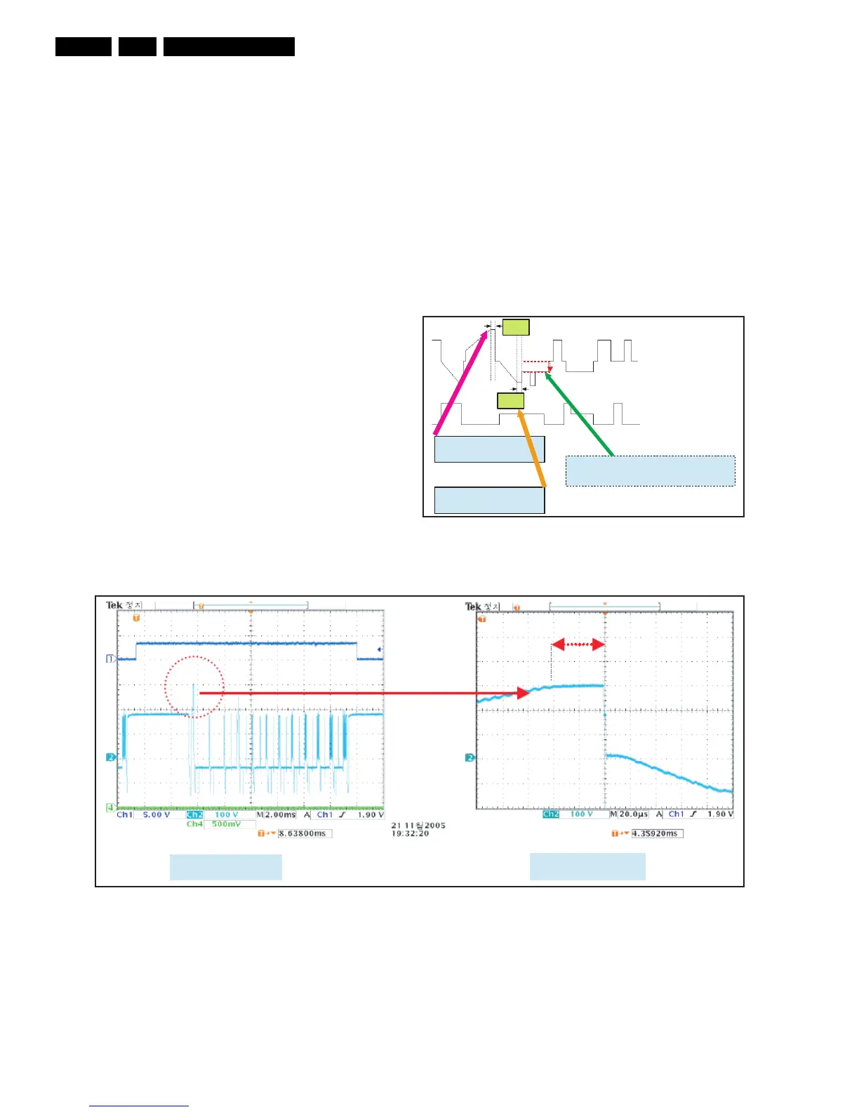
4. Adjust the flat time of the rising ramp of the 1st subframe to
40 µS with VR5001 (see Figure “Rising ramp flat time
adjustment”).
5. Adjust the flat time of the falling ramp of the 1st subframe
to 16 µs with VR5002 (see Figure “Falling ramp flat time
adjustment”).
• This is a difficult adjustment.
• It is easier and more accurate to do the following:
– Count 3 pulses between A and B;
– Set the difference between A and B to 40 V; the
time between C and D will then automatically be
set to approximately 16 µS
– Settings of the oscilloscope: vertically 20VDC/div,
horizontally 10 µS/div.
6. Check with the oscilloscope if the voltage of Vsch is -38 V
(see Figure “Y-scan H waveform”).
Special notice: It is very important, that you execute this
adjustment on the 1st Sub-Field (SF) of the 1st Frame of the
Reset waveform.
Figure 8-1 Waveform adjustment (Y-Board)
Figure 8-2 Rising ramp flat time adjustment (Y-Board)
G_14992_001.eps
190106
Adjust VR5001 to set the time of
Yrr( Rising Ramp ) 40
µs
Adjust VR5002 to set the time
of Yfr (Falling Ramp_1st) 16
µs
Adjust VR5000 to set the voltage to -38 V.This
alignment can be executed by using a DMM, the
+ of the DMM on Y-scan H test point
40 µs
16 µs
Ch2 = 100V/2ms/div
Ch2 = 100V/20µs/div
G_14992_002.eps
190106