Alignments
EN 71SDI PDP 2K6 8.
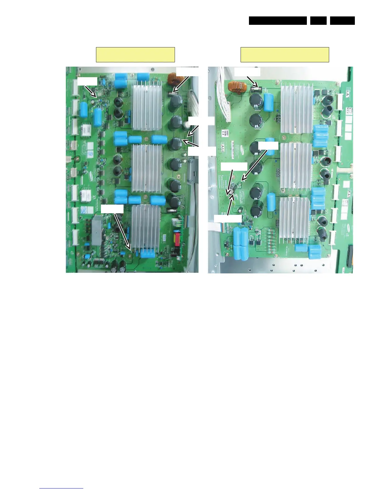
Figure 8-12 Location of the test points for the supply voltages - 63" HD v4
8.2 Waveform Alignments 42” SD v5
1. Set the pattern to Full White (put a jumper on pins 1 and 2
of CN2012 of the Logic Board).
2. Check the waveform using an Oscilloscope.
• Triggering through V_TOGG of the LOGIC Board (see
Figure “Logic PWB”).
• Connect the “OUT240” test point, located at the centre
of the Y-buffer PWB, to the other channel, and then
check the first Subfield waveform of one TV-Field.
• Check the waveform by adjusting the Horizontal
Division of the oscilloscope.
3. Adjust the waveform of the rising ramp with VR5000 (see
Figure “Rising ramp waveform adjustment”).
4. Adjust the waveform of the falling ramp with VR5001 (see
Figure “Falling ramp waveform adjustment”).
G_16380_057.eps
171006
Y-main X-main
Vs [F5002]
Vcc [F5000]
Vdd [F5001]
Vs [F4003]
Ve [TP]
Vcc [F4000]
Vdd [F4001]
Vset [TP]
Vsch [TP]
 Loading...