Do you have a question about the Phoenix Contact Axioline F and is the answer not in the manual?
Explains warning symbols and signal words used in the manual.
Defines the target audience for using the products and their required expertise.
Specifies the correct usage of Axioline F controllers and modules and liability limitations.
States that modifications to hardware and firmware are not permitted.
Lists and describes various documents related to the Axioline F product group.
Explains how to download product documentation and updates from the internet.
Clarifies the scope and content of this specific user manual for Axioline F systems.
Introduces the Axioline F system's modular architecture, flexibility, and Ethernet compatibility.
Details the key characteristics of Axioline F: fast, robust, and easy to use with various benefits.
Explains the components and assembly of an Axioline F station on a DIN rail.
Describes the components of an Axioline F I/O module and its available versions.
Guides users on how to find the latest approvals for Axioline F modules via the website.
Explains how the order designation identifies a module's function, type, and features.
Describes the function, types (Class 1000/3000, PLCnext), and applications of Axioline F controllers.
Explains the role of bus couplers in linking networks to Axioline F stations and supported protocols.
Lists various types of input and output modules (digital, analog, temp., safety) available for Axioline F.
Details the characteristics and testing of Axioline F modules for extreme ambient conditions (-40°C to +70°C).
Describes safety modules for use in safe systems like PROFIsafe with digital inputs or outputs.
Explains the use of power modules to provide or boost the bus voltage (UBus).
Describes the function of masters in integrating lower-level systems into the Axioline F station.
Illustrates the various housing types (e.g., 2F, 1F, 1H, 2H) available for Axioline F modules.
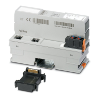
Shows the design and identifies key components of Axioline F controllers, bus couplers, and I/O modules.
Provides nominal dimensions for AXC controller, bus coupler, and I/O module housings.
Describes Axioline F bus base modules, their function, and types.
Illustrates various Axioline F connector versions and their physical dimensions.
Explains the color coding for housing, connectors, and module function identification.
Describes methods for custom marking of modules and connectors using marker strips or labels.
Instructions for unpacking modules and checking the packing slip for installation details.
General safety precautions for handling modules, including electrostatic discharge (ESD) protection.
General information on mounting location, DIN rail compatibility, and module installation.
Lists necessary tools, like a screwdriver, for module removal.
Guidelines on the sequence of installing modules on the DIN rail to ensure functionality.
Details the limit on the number of modules that can be installed per Axioline F station.
Discusses power supply requirements and current consumption limits for station operation.
Information on system limits for bus couplers and controllers that may affect configuration.
Notes for modules installed to the left of the controller, requiring specific installation notes.
General instructions for mounting Axioline F modules without special tools.
Step-by-step guide for mounting controllers and bus couplers onto the DIN rail.
Instructions for mounting Axioline F I/O modules onto the bus base modules.
Procedures for removing controllers, bus couplers, and I/O modules individually from the station.
Steps to remove network, supply, and I/O connectors or cables from modules.
Steps to remove bus base modules from the DIN rail after module removal.
How to release, remove, and insert connectors properly into modules.
General steps for replacing a module, referencing removal and mounting procedures.
Specifies required space for cable routing, connectors, and module mounting.
Overview of connection types, cable requirements, and terminal point current limits for Axioline F.
Details permissible conductor sizes and stripping lengths for different connection technologies.
Specifies stripping and insertion lengths and notes on ferrule usage.
Explains the terminal points, spring levers, and touch connections on connectors.
Instructions for connecting solid and stranded unshielded cables using Push-in technology.
Steps for connecting shielded cables, including stripping and grounding the shield.
How to remove cables from terminal points using the spring lever mechanism.
Explains the required supply voltages (UL, UBus) for an Axioline F station and their sources.
Guidelines for selecting appropriate power supply units based on application currents and bus configuration.
How the controller/bus coupler provides communications (UL) and local bus (UBus) power.
Use of power modules to provide or boost the UBus voltage when maximum load is reached.
Describes how I/O modules receive their individual supply voltage (UI/UO/UIO/UA).
Explains jumpers for potential forwarding and fusing in power connectors for supply distribution.
How to supply modules in parallel to handle higher current consumption than 8A.
General instruction for connecting the network cable to the controller or bus coupler.
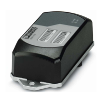
How to connect a PC to controllers/bus couplers via USB for IP address assignment and diagnostics.
Overview of connection technologies (1, 2, 3, 4-wire) for sensors and actuators.
Tables showing connection pin assignments for digital input and output modules.
Explains 1, 2, 3, and 4-wire connection technologies for sensors and actuators.
Explains 1-wire sensor and actuator connections with circuit diagrams.
Explains 2-wire sensor and actuator connections with circuit diagrams.
Explains 3-wire sensor and actuator connections with circuit diagrams.
Explains 4-wire sensor connections with circuit diagrams.
How to connect PLC relays using the FLK connection on specific output modules.
Example connections for redundant use of digital inputs and outputs for higher availability.
Example connection for redundant use of digital inputs.
Example connection for redundant use of digital outputs.
Distinguishes between functional ground (FE) and protective earth ground (PE).
Explains protective earth grounding and its role in user safety against hazardous voltages.
Details functional ground for interference immunity in the 24V area, connecting to the DIN rail.
Guidelines for using shielded cables with Axioline F modules for noise reduction.
Specifics for shielding analog signals and twisted pair cables, connecting to shield bus.
How to use the shield connection set for grounding analog signal cables.
Method for connecting shielding to a busbar for optimal signal transmission path.
Integrating analog shielding with central equipotential bonding at the control cabinet entry.
Details diagnostic indicators (D, UA, E1, E2) on controllers for status and errors.
Explains power supply (UL), network (RDY, D, E), and module indicators on bus couplers.
Describes LEDs on power and I/O connectors for diagnostics and status.
How local diagnostics map to PDI object 0018hex (DiagState) for error reporting.
Explains process data structure, significance, and Motorola format in Axioline F.
Details the PDI channel for parameter, diagnostic data, and service access.
Explains how parameters are saved in flash memory and RAM and their limitations.
Lists Phoenix Contact software (PROJECT complete, Startup+, PC Worx) supporting Axioline F.
Describes the PROJECT complete software for control cabinet planning, marking, and ordering.
Explains FDT/DTM concepts and the Startup+ software for parameterization and diagnostics.
Details programming software options like PC Worx, PC Worx Express, and PLCnext Engineer.
General technical data for Axioline F stations and notes on observing additional documentation.
Lists general environmental, electrical (protection class, clearances), and mechanical specifications.
EMC immunity tests, radio disturbance characteristics, and interface data for low-voltage modules.
Details 24V supply specifications, ripple, voltage range, and local bus supply.
Information on Axioline F connectors, Push-in connection, contact capacity, and cable cross sections.
Information on ordering Axioline F modules and accessories like tools and marking materials.
Lists materials for shield connection, including shield connection sets, clamps, and busbars.
Explains temperature derating for modules operating at elevations above 3000 meters.
Describes transmission speed and the fast, cyclic, equidistant local bus communication.
Provides the formula for calculating local bus cycle time and an example.
Details the components contributing to the overall system response time, from input to output.
Defines terms related to processing times, such as conversion time and update time in the Axioline F system.
Introduces communication objects (PDI objects) and how they are accessed via services.
How to access PDI objects using function blocks in PC Worx via an installable library.
Lists standard objects for identification, diagnostics, device management, and descriptions.
Describes objects (DiagState) that provide diagnostic state and error information.
Explains synchronization options and requirements for the Axioline F system.
Explains module behavior during power-on and when process data is missing (substitute values).
Lists all figures included in the manual with their corresponding page numbers.
Lists all tables included in the manual with their corresponding page numbers.
Provides an alphabetical index of topics covered in the manual for quick reference.
| Brand | Phoenix Contact |
|---|---|
| Model | Axioline F |
| Category | Control Unit |
| Language | English |