EasyManua.ls Logo

Phoenix Contact QUINT-PS-100-240AC/24DC/2.5 User Manual

Phoenix Contact QUINT-PS-100-240AC/24DC/2.5
11 pages
To Next Page IconTo Next Page
Page #1 background imageLoading...
Page #1 background image
© PHOENIX CONTACT - 12/2005
Data Sheet
INTERFACE
100028_04_en 1
PHOENIX CONTACT GmbH & Co. KG • 32823 Blomberg • Germany
Phone: +49 - 52 35 - 30 0 • Fax: +49 - 52 35 - 34 12 00 • www.phoenixcontact.com
www.phoenixcontact.com/salesnetwork
QUINT-PS-100-240AC/24DC/2.5
Description
QUINT POWER devices are 60...960 W DC power supply
units for universal use. This is ensured by the wide-range
input, single and three-phase versions, and an international
approval package.
QUINT POWER stands for guaranteed supply: powerful
capacitors ensure mains buffering of more than 20 ms at full
load.
All three-phase devices provide the full output power, even
in the event of a continuous phase failure.
The POWER BOOST power reserve starts loads with high
inrush currents and ensures that fuses are reliably tripped.
Preventive function monitoring diagnoses impermissible
operating states and minimizes downtimes in your system.
An active transistor output and a floating relay contact are
used for remote monitoring.
All QUINT POWER devices are idling-proof and
short-circuit proof, and are available with a regulated and
adjustable output voltage of 12, 24, and 48 V DC with output
currents of 2.5, 5, 10, 20, 30, and 40 A.
Power supply units for use in Ex Zone 2, uninterruptible
solutions, AS-i power supply units, and a QUINT diode
complete the product range.
QUINT POWER is a built-in device. Installation
and startup must only be carried out by
qualified personnel. The relevant country-
specific regulations (e.g., VDE, DIN) must also
be observed.
Danger
The device contains dangerous live elements and high levels of stored energy.
Never carry out work when the power is turned on.
Risk of burns
The housing temperature can reach high values depending on the ambient temperature and the load of the
device.
Make sure you always use the latest documentation.
It can be downloaded at www.download.phoenixcontact.com
.
A conversion table is available on the Internet at
www.download.phoenixcontact.com/general/7000_en_00.pdf
.
This data sheet is valid for all products listed on the following page:
Single-Phase Primary-Switched Power Supply Unit
Question and Answer IconNeed help?

Do you have a question about the Phoenix Contact QUINT-PS-100-240AC/24DC/2.5 and is the answer not in the manual?

Phoenix Contact QUINT-PS-100-240AC/24DC/2.5 Specifications

General IconGeneral
Output Current2.5 A
Power60 W
Mounting TypeDIN Rail
Protection ClassIP20
Input Voltage100-240 V AC
Output Voltage24 V DC
Operating Temperature-25 °C ... 70 °C ( > 60 °C Derating: 2.5%/K)

Summary

Description of QUINT POWER Devices

Ordering Data

Product Information

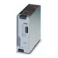
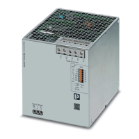
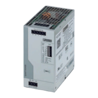
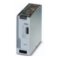
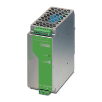
Details about the single-phase primary-switched power supply unit.

Accessories

Information on assembly adapters for QUINT POWER units.

Technical Data Overview

Input Data Specifications

Details on input voltage, current, frequency, and protection.

Output Data Specifications

Details on output voltage, current, derating, and limits.

Active DC OK Signal Output

Information regarding the active DC OK signal output functionality.

Additional Technical Data

Floating DC OK Signal Output

Information regarding the floating DC OK signal output functionality.

General Device Data

Details on insulation, mounting, protection, weight, and housing.

Status Indicators

Information on the DC OK status indicator LED.

Climatic Data

Ambient conditions, humidity, vibration, and shock resistance.

Certifications and Standards

List of relevant certifications and standards compliance.

EMC and Low Voltage Directive Conformance

Noise Immunity Tests

Details on noise immunity test requirements and criteria (EN 61000-6-2).

Noise Emission Tests

Details on noise emission test requirements and criteria (EN 61000-6-3).

Device Structure and Elements

Safety Instructions and Operation

Critical Safety Warnings

Essential warnings regarding live elements, stored energy, and burns.

Installation Guidelines

Instructions for safe and proper installation of the power supply.

Convection and Spacing

Requirements for sufficient spacing for adequate cooling.

Mounting and Assembly

Mounting Position Details

Illustrations and dimensions for narrow and flat mounting positions.

Assembly Procedure

Instructions for attaching the module to a DIN rail.

Removal Procedure

Instructions for detaching the module from a DIN rail.

Network Connection

Cable Connection Guidelines

Input Wiring

Instructions for connecting the AC input terminals.

Fuse Protection

Information on internal and recommended fuse protection.

Primary Side Protection

Requirements for protecting the primary side of the device.

Output Configuration and Protection

Output Terminal Connection

Instructions for connecting the output terminals.

Secondary Side Protection

Details on secondary side short-circuit and idling protection.

Signaling and Monitoring

Explanation of DC OK outputs and status LED.

Signal Loop and Status Indication

Signal Loop Combination

How to combine signal outputs for monitoring devices.

DC OK LED Status

Explanation of the DC OK LED and its local function evaluation.

Output Functionality

Output Characteristic Curve

Graph and explanation of output current versus voltage characteristics.

Operational Performance

Temperature Response

How ambient temperature affects the output current capability.

Parallel Operation for Redundancy

Guidelines for parallel connection to achieve redundancy.

Parallel Operation for Increased Power

Guidelines for parallel connection to increase output power.

Related product manuals