EasyManua.ls Logo

Phoenix Contact QUINT4-PS/3AC/24DC/10 User Manual

Phoenix Contact QUINT4-PS/3AC/24DC/10
51 pages
To Next Page IconTo Next Page
Page #1 background imageLoading...
Page #1 background image
1Description
Power supply unit
QUINT4-PS/3AC/24DC/10
© PHOENIX CONTACT
Data sheet
QUINT POWER power supplies with SFB Technology and
preventive function monitoring ensure superior system
availability.
Powerful
SFB technology: 6 times the nominal current for 15ms
Power reserves:
Static boost of up to 125%(P
N
) for a sustained period
Dynamic boost of up to 200%(P
N
) for 5s
Robust
–Mains buffering 20ms
High degree of electrical immunity, thanks to integrated
gas-filled surge arrester (6kV)
Preventive
Comprehensive signaling:
Analog signal, digital signal, relay contact, LED bar
graph
Can be ordered pre-configured
Perform configuration online and order 1 or more units
Technical data (short form)
Input voltage range 3x 400 V AC ... 500 V AC
-20%...+10%
2x 400 V AC ... 500 V AC
-10 % ... +10 %
Mains buffering 22 ms (3x 400 V AC)
22 ms (3x 480 V AC)
Nominal output voltage (U
N
) 24 V DC
Setting range of the output voltage
(U
Set
)
24 V DC ... 29.5 V DC
Nominal output current (I
N
)
Static Boost (I
Stat.Boost
)
Dynamic Boost (I
Dyn.Boost
)
Selective Fuse Breaking (I
SFB
)
10 A
12.5 A
20 A
60 A (15 ms)
Output power (P
N
)
Output power (P
Stat. Boost
)
Output power (P
Dyn. Boost
)
240 W
300 W
480 W
Efficiency typ. 93 % (400 V AC)
typ. 92.6 % (480 V AC)
Residual ripple < 75 mV
PP
MTBF (IEC 61709, SN 29500) > 654000 h (40 °C)
Ambient temperature (operation) -25 °C ... 70 °C
-40°C (startup type tested)
> 60 °C Derating: 2.5 %/K
Dimensions W/H/D 50 mm / 130 mm / 125 mm
Weight 0.9 kg
All technical values are nominal values at an input voltage of 3x 400VAC. They refer to a room temperature
of 25°Cand 70%relative humidity at 100m above sea level.
107104_en_01
2018-09-04
Question and Answer IconNeed help?

Do you have a question about the Phoenix Contact QUINT4-PS/3AC/24DC/10 and is the answer not in the manual?

Phoenix Contact QUINT4-PS/3AC/24DC/10 Specifications

General IconGeneral
BrandPhoenix Contact
ModelQUINT4-PS/3AC/24DC/10
CategoryPower Supply
LanguageEnglish

Summary

1 Description

Powerful

SFB technology and power reserves.

Robust

Mains buffering and electrical immunity.

Preventive

Comprehensive signaling and pre-configuration.

3 Ordering data

Accessories

Lists various accessories for the power supply.

4 Technical data

Input data

Details input voltage range, frequency, and current draw.

Mains buffering

Specifies buffering time for power interruptions.

Switch-on time

Defines the power supply's switch-on time.

Protective circuit

Mentions surge protection components.

Switch-on current surge limitation

Details surge current limitation after 1ms.

Input protection, AC

Specifies AC input protection requirements.

Electric strength of the insulation

Details insulation test voltages.

Input connection data

Specifies connection methods and conductor data.

Output data

Nominal output voltage (UN)

Specifies the nominal DC output voltage.

Setting range of the output voltage (Uset)

Defines the adjustable output voltage range.

Nominal output current (IN)

States the maximum continuous output current.

Static Boost (IStat.Boost)

Details the sustained higher output current capability.

Dynamic Boost (IDyn.Boost)

Describes the temporary higher output current.

Selective Fuse Breaking (ISFB)

Specifies the SFB current for tripping protection.

Short-circuit-proof

Confirms electronic short-circuit protection.

No-load proof

Confirms operation without a load.

Residual ripple (with nominal values)

Specifies the maximum output voltage ripple.

Connection in parallel

Notes possibility of parallel connection for redundancy.

Connection in series

Notes possibility of series connection for voltage increase.

Output connection data

Specifies connection methods and conductor data for output.

LED signaling

Explains LED indicators for output status.

Signal contact (configurable)

Details configurable signal outputs.

Reliability

General data

Degree of protection

Specifies the IP protection rating.

Dimensions W / H / D

Provides physical dimensions of the unit.

Power dissipation

Details power consumption in various modes.

Efficiency

Shows efficiency percentages at different loads.

Ambient conditions

Ambient temperature (operation)

Defines operating temperature range with derating.

Installation height

Details altitude limits for operation.

Standards

Overvoltage category

Lists overvoltage categories for standards.

Rail applications

Lists relevant rail application standards.

Approvals

UL

Lists UL certifications.

CSA

Lists CSA certifications.

Electromagnetic compatibility

Electrostatic discharge EN 61000-4-2

Specifies ESD immunity requirements.

Electromagnetic HF field EN 61000-4-3

Specifies RF field immunity requirements.

Fast transients (burst) EN 61000-4-4

Specifies transient immunity requirements.

Surge voltage load (surge) EN 61000-4-5

Specifies surge voltage immunity.

Conducted interference EN 61000-4-6

Specifies conducted interference immunity.

Voltage dips EN 61000-4-11

Specifies immunity to voltage dips.

Asymmetrical conducted disturbance variables EN 61000-4-16

Specifies asymmetrical conducted disturbance immunity.

Attenuated oscillating wave EN 61000-4-18

Specifies attenuated oscillating wave immunity.

5 Safety and installation notes

CAUTION: Before startup, observe the following

Important pre-startup safety checks.

DANGER: Hazardous voltage

Warning about hazardous internal voltages.

CAUTION: Hot surface

Warning about potential hot surfaces.

6 High-voltage test (HIPOT)

6.1 High-voltage dielectric test (dielectric strength test)

Explains the dielectric strength testing process.

6.3.1 Performing high-voltage testing

Details procedures for performing HV testing.

6.3.2 Disconnecting the gas-filled surge arrester

Instructions for disconnecting surge arrester for testing.

7 Structure of the power supply

7.1 Function elements

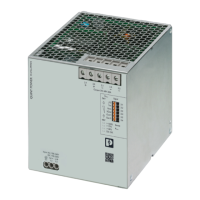
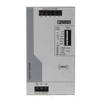
Identifies and describes the main components of the power supply.

7.2 Device dimensions

7.3 Keep-out areas

7.4 Block diagram

Key

Explains symbols used in the block diagram.

8 Mounting/removing the power supply

8.1 Mounting the power supply unit

Step-by-step guide for mounting the unit.

8.2 Removing the power supply unit

Step-by-step guide for removing the unit.

8.3 Retrofitting the universal DIN rail adapter

Information on mounting the DIN rail adapter at 90°.

8.3.2 Mounting the universal DIN rail adapter

Instructions for mounting the DIN rail adapter on the left side.

8.4 Retrofitting the universal wall adapter

Details on using wall adapters for mounting.

8.4.1 Mounting the UWA 182/52 universal wall adapter

Steps to mount the UWA 182/52 adapter.

8.5 Fix connection wiring to the power supply

How to secure connection wiring using cable binders.

9 Device connection terminal blocks

9.1 Input

Describes AC input connection and network configurations.

9.2 Protection of the primary side

Details primary side protection requirements.

9.3 Output

Explains output voltage adjustment.

9.4 Protection of the secondary side

Covers secondary side protection and fault behavior.

10 Output characteristic curves

Application

Lists different application areas for output curves.

Your benefits

Highlights benefits of each characteristic curve.

Characteristics

Lists available output characteristic curves.

10.1 U/I Advanced output characteristic curve

Details the advanced U/I characteristic curve.

10.2 Smart HICCUP output characteristic curve

Explains the Smart HICCUP curve and its behavior.

10.3 FUSE MODE output characteristic curve

Describes the FUSE MODE curve and its shutdown behavior.

11 Configuring the power supply

11.1 Configuration with PC software

Steps to configure via PC software using NFC adapter.

11.2 Configuring the power supply

General procedure for power supply configuration.

11.3 Configuration with NFC-capable mobile terminal device

How to configure using a mobile app via NFC.

11.4 Ordering a configured power supply

Information on ordering pre-configured units.

12 Boost currents

12.1 Static Boost

Details sustained higher output current capability.

12.2 Dynamic Boost

Explains temporary higher output current and recovery.

12.2.3 Example: Determining the recovery time (tpause)

Example calculation for recovery time.

13 SFB technology

13.1 Tripping circuit breakers

How SFB technology trips circuit breakers.

13.2 Tripping a fuse

How SFB technology trips fuses.

13.3 SFB configuration

Framework conditions for SFB configuration.

13.4 Maximum distance between the power supply and load

Specifies maximum cable lengths for SFB operation.

13.4.2 Thermomagnetic circuit breaker, type: Siemens 5SY, ABB S200

Max distance table for Siemens/ABB circuit breakers.

13.4.3 Fuse, type: Cooper Bussmann GMA XA, GMC XA

Max distance table for Cooper Bussmann fuses.

14 Signaling

14.1 Location and function of the signaling elements

Identifies signaling elements and LEDs.

14.1.1 Floating signal contact

Details the floating signal contact function.

14.1.2 Active signal outputs, digital

Explains digital signal outputs.

14.1.3 Active analog signal output

Explains analog signal output.

14.2 Preventive function monitoring

Shows default signal settings for various parameters.

14.3 Output voltage

Explains output voltage signaling.

14.3.2 Output current

Explains output current signaling.

14.3.3 Output power

Explains output power signaling.

14.3.5 Early warning of high temperature

Explains high temperature warning signaling.

14.3.6 Voltage limitation active

Explains voltage limitation active signaling.

14.3.7 Input voltage OK

Explains input voltage OK signaling.

14.3.8 Phase monitoring (3AC operation)

Explains phase monitoring signaling.

14.4 Remote input

Explains the remote input function.

14.5 LED status indicators

Details the function of front panel LED indicators.

14.6 U/I Advanced characteristic curve signaling

Shows default signaling for U/I Advanced curves.

14.7 SMART HICCUP characteristic curve signaling

Shows default signaling for SMART HICCUP curves.

14.8 FUSE MODE characteristic curve signaling

Shows default signaling for FUSE MODE curves.

14.9 SLEEP MODE signaling

Describes signaling behavior in SLEEP MODE.

14.10 Special immunity for the signal level

Covers special immunity requirements for signal connections.

15 Operating modes

15.1 Series operation

How to connect two units in series for higher voltage.

15.2 Parallel operation

How to connect units in parallel for increased power or redundancy.

15.2.1 Redundancy operation

Details redundant operation for reliability.

15.2.2 Increased power

Explains parallel connection for increased output power.

16 Derating

16.1 Ambient temperature

Explains output power reduction due to high ambient temperatures.

16.2 Input voltage

Discusses output power in 2AC operation.

16.3 Installation height

Explains output power reduction due to installation height.

16.4 Position-dependent derating

Details derating based on mounting orientation.

16.4.1 Normal mounting position

Derating curves for normal mounting.

16.4.2 Rotated mounting position 90° Z-axis

Derating curves for 90° Z-axis mounting.

16.4.3 Rotated mounting position 180° Z-axis

Derating curves for 180° Z-axis mounting.

16.4.4 Rotated mounting position 270° Z-axis

Derating curves for 270° Z-axis mounting.

16.4.5 Rotated mounting position 90° X-axis

Derating curves for 90° X-axis mounting.

16.4.6 Rotated mounting position 270° X-axis

Derating curves for 270° X-axis mounting.

Related product manuals