Do you have a question about the Phoenix Contact QUINT4-PS/1AC/48DC/10 and is the answer not in the manual?
Highlights SFB technology, static and dynamic boost for enhanced power delivery.
Emphasizes mains buffering and high electrical immunity with surge arrester.
Details comprehensive signaling via analog, digital, relay, and LED bar graph.
Explains the ability to order pre-configured units and perform online configuration.
Lists and describes optional accessories for mounting, configuration, and protection.
Covers input voltage range, electric strength, frequency range, and current draw.
Details AC input protection requirements and electrical insulation test values.
Presents the power factor graph showing its behavior with varying output current.
Specifies crest factor values and parameters for input terminal connections.
Defines output connection methods, LED indicators, and signal contact functions.
Covers signal connection specifics, MTBF, life expectancy, general data, and power dissipation.
Details component life expectancy and power dissipation characteristics.
Details ambient temperature, humidity, installation height, vibration, and shock requirements.
Specifies installation height, vibration, shock, pollution degree, and climatic class.
Lists the UL, CSA, and Shipbuilding approvals for the power supply unit.
Details conducted and radiated noise emission standards and performance requirements.
Introduces immunity standards and requirements for industrial environments.
Specifies requirements for conducted interference and power frequency magnetic fields.
Details voltage dip and fast transient immunity requirements according to EN 61000-4-11 and -4-4.
Covers additional immunity standards for pulse-shape, damped oscillating, and ring wave disturbances.
Provides essential safety notes, including handling hazardous voltage and hot surfaces.
Highlights dangers of hazardous voltage and hot surfaces on the power supply housing.
Explains the dielectric strength test for ensuring user safety and permanent isolation.
Describes factory routine tests and customer-performed high-voltage dielectric tests.
Details performing high-voltage tests and safely disconnecting the gas-filled surge arrester.
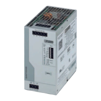
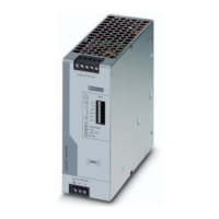
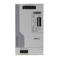
Illustrates and describes the operating and indication elements on the power supply.
Presents the main device dimensions and shows different mounting configurations.
Defines minimum keep-out areas around the device based on output capacity.
Instructions for snapping the power supply onto a DIN rail and removing it.
Guide for retrofitting the universal DIN rail adapter for horizontal mounting.
Details on attaching the universal wall adapter for secure mounting in vibrating environments.
Steps for mounting the universal DIN rail adapter onto the left side of the device.
Instructions for mounting the UWA 182/52 universal wall adapter to the power supply.
Steps for mounting the UWA 130 two-piece universal wall adapter onto the power supply.
Guidance on using cable binders to secure connection wiring to the housing.
Illustrates input connection types for TN-S, TN-C, TT, and IT power grids.
Explains protection for the primary AC supply and the secondary DC supply.
Table showing suitability of characteristic curves for different applications like normal load and system extension.
Details applications, behavior, and diagrams for the U/I Advanced output characteristic curve.
Explains the Smart HICCUP curve for thermal load management and overload protection.
Describes the FUSE MODE curve for permanent DC output shutdown on overload.
Covers hardware and software requirements for configuring the power supply using a PC.
Details using the QUINT POWER app and NFC for configuration on mobile devices.
Information on ordering customer-specific, pre-configured power supplies.
Explains the sustained static boost (up to 125% of nominal current).
Describes the dynamic boost (up to 200% for 5s) for high loads.
Provides tables to determine required recovery time (tpause) after dynamic boost.
Explains how SFB technology quickly trips miniature circuit breakers on the secondary side.
Describes how SFB technology aids in tripping fuses based on melting integral (I²t).
Details calculation parameters for determining maximum cable lengths for tripping.
Provides tables for maximum distances between power supply and circuit breakers.
Presents tables for maximum distances between power supply and different types of fuses.
Identifies the position and basic function of signaling elements like LEDs and contacts.
Details configurations for relay contact, digital, and analog signal outputs.
Customizable signal options for monitoring output voltage, current, power, and operating status.
Provides specific use cases and explanations for each signal type (voltage, current, power, etc.).
Explains wiring for remote control and switching the power supply to SLEEP MODE.
Describes the meaning of the DC OK and Pout LEDs under various operating conditions.
Shows standard signal assignments for U/I Advanced and Smart HICCUP curves.
Details signaling for FUSE MODE and the status indications in SLEEP MODE.
Covers surge protection implementation for signal levels in various environments.
Instructions for connecting two power supplies in series to double output voltage.
Guidelines for connecting multiple power supplies in parallel for increased power or redundancy.
Details on using two power supplies for 1+1 redundancy and monitoring.
Explains parallel connection for increased output current and load capacity.
Specifies derating for ambient temperatures above 60°C and sustained boost at 40°C.
Details derating applied for input voltages below the nominal range.
Covers derating considerations for operation at installation heights above 2000 m.
Explains derating for non-standard mounting positions and provides characteristic curves.
| Brand | Phoenix Contact |
|---|---|
| Model | QUINT4-PS/1AC/48DC/10 |
| Category | Power Supply |
| Language | English |