Do you have a question about the Phoenix Contact QUINT4-PS/1AC/24DC/40 and is the answer not in the manual?
Highlights SFB Technology, boost capabilities, signaling functions, and long service life for superior system availability.
Presents key technical specifications in a short form table, including input/output ranges and boost currents.
Details the primary QUINT POWER supply, its type, order number, and configuration options.
Lists compatible accessories like wall adapters, NFC programming adapters, and surge protection devices.
Covers input voltage range, frequency, electric strength, and current draw characteristics.
Details output voltage, current, connection methods, conductor sizes, and torque specifications.
Specifies input protection requirements using circuit breakers and fuses based on current.
Outlines insulation strength ratings and various dielectric test types for safety compliance.
Explains the function of status LEDs indicating output voltage, power, and system health.
Describes configurable digital, analog, and relay signal outputs for system monitoring.
Provides Mean Time Between Failures (MTBF) and component life expectancy data.
Includes physical dimensions, weight, degree of protection, and flammability class.
Details operating temperature ranges, humidity, and installation height limitations.
Specifies overvoltage categories and degree of pollution for environmental compliance.
Lists relevant international and industry standards for power supplies and electrical safety.
Summarizes certifications and approvals from bodies like UL, CSA, SIQ, and DNV GL.
Covers standards for conducted and radiated noise emissions in residential and industrial environments.
Details immunity requirements for electrostatic discharge, HF fields, and transient bursts.
Addresses immunity to surge voltage, conducted interference, and voltage dips.
Covers immunity requirements for magnetic fields and oscillating waves.
Defines safety alert symbols, warning indicators, and note conventions used in the document.
Provides critical safety warnings regarding electric shock, hot surfaces, and potential damage.
Explains the purpose and methods of dielectric strength testing for electrical safety.
Covers dielectric tests performed during manufacturing and customer testing procedures.
Guidelines and precautions for safely conducting high-voltage tests on the power supply.
Instructions for disconnecting and reconnecting the gas discharge tube for testing purposes.
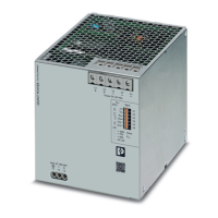
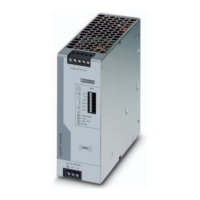
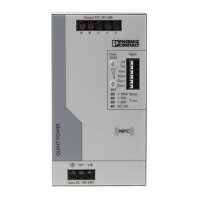
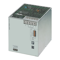
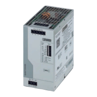
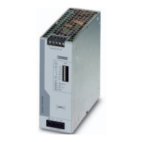
Identifies key components, indicators, and connection terminals on the power supply unit.
Provides unit dimensions and information on DIN rail mounting compatibility.
Specifies minimum clearance distances around the power supply for proper heat dissipation.
Step-by-step guide for attaching the power supply to a standard DIN rail.
Instructions for safely detaching the power supply unit from the DIN rail.
Details disassembly and retrofitting procedures for the universal DIN rail adapter.
Guides on attaching the universal DIN rail adapter to the left side of the power supply.
Instructions for mounting the power supply using universal wall adapters for stability.
Specific steps for mounting UWA 182/52 and UWA 130 two-piece universal wall adapters.
Describes using cable binders to manage and secure connection wiring for safety.
Details AC input connections, network types (TN-S, TN-C, TT, IT), and terminal assignments.
Covers primary circuit protection requirements, including fuse placement and safety.
Explains output voltage control via buttons and secondary side protection mechanisms.
Details the U/I Advanced curve for SFB, motor loads, and system extension applications.
Explains the Smart HICCUP curve for thermal management and overload response behavior.
Guides on configuring the power supply via PC software and the NFC interface.
Details using the NFC interface for setup, data transfer, and parameter configuration.
Describes configuration using a mobile device app and the NFC interface.
Explains the process for ordering factory-configured power supplies for specific applications.
Details sustained static boost capability up to 112% at ambient temperatures up to 40°C.
Explains dynamic boost for temporary high loads (150%) and required recovery times.
Provides tables to determine the required recovery time for dynamic boost based on load.
How SFB technology quickly trips circuit breakers, minimizing voltage dips for parallel loads.
Explains fuse tripping via SFB current and the melting integral (I²t) for fast response.
Outlines conditions for effective SFB operation, including cable length and fuse characteristics.
Maximum cable lengths for Phoenix Contact CB TM1 SFB circuit breakers with various cross-sections.
Identifies and explains the purpose of LEDs and signal terminals on the power supply.
Explains the floating contact's response to output voltage undershoot.
Details digital outputs for monitoring voltage and power status.
Describes the 4-20 mA analog output for continuous workload monitoring.
Monitors output voltage status relative to preset thresholds.
Signals when output current exceeds configured limits.
Indicates when output power surpasses set thresholds.
Signals exceeded operating hours and impending temperature derating.
Signals surge protection activation and input voltage status.
Controls power supply ON/OFF and SLEEP MODE via remote input.
Explains the meaning of the DC OK and Pout status LEDs for system monitoring.
Standard signaling assignments for the U/I Advanced characteristic curve.
Standard signaling assignments for the SMART HICCUP characteristic curve.
Standard signaling assignments for the FUSE MODE characteristic curve.
Describes the indicator states and signals when the unit is in SLEEP MODE.
Details surge protection requirements for signal connections in various applications.
How to connect two power supplies in series to achieve higher output voltage.
Guidelines for connecting units in parallel for increased power or redundancy.
Explains 1+1 redundancy and decoupling methods for enhanced reliability.
Details connecting multiple units in parallel for higher output current capacity.
Describes power reduction at high ambient temperatures (>60°C) with a 2.5%/K factor.
Details derating factors based on input voltage conditions and temperature.
Explains output power adjustments for varying installation altitudes above 2000m.
Output power curves showing derating for standard horizontal mounting based on temperature.
Output power curves for various rotated mounting positions (e.g., 90° Z-axis) based on temperature.
Output power curves for 180° Z-axis rotated mounting orientation.
Output power curves for 270° Z-axis rotated mounting orientation.
Output power curves for 90° X-axis rotated mounting orientation.
Output power curves for 270° X-axis rotated mounting orientation.
| Brand | Phoenix Contact |
|---|---|
| Model | QUINT4-PS/1AC/24DC/40 |
| Category | Power Supply |
| Language | English |