FAN STATIC RESET KIT
75 Discovery Way • Acton, Massachusetts 01720 • Telephone (978) 795-1285 • Fax (978) 795-1111
©2010 Phoenix Controls Corporation. Specifications subject to change without notice. Rev. 5/10 MKT-0266 MPC-1480 FAN STATIC RESET KIT—1 OF 12
SPECIFICATIONS (continued)
Temperature
Error
±2% of Span (Over the
Operating Temperature Range)
Enclosure
Humidity 95% non-condensing
Material Polycarbonate
Material Rating UL94, V-0
Enclosure Rating IP66
Dimensions 4.15" x 5.00" x 2.50"
(105.4 mm x 127 mm x 63.6 mm)
Tubing
ID/OD 1/8" / 1/4" (3.2 mm / 6.4 mm)
Wall Hardness Shore A 70
Temperature
Range
-137° F to 738° F
(-94° C to 392° C)
Tensile Strength 1350 PSI
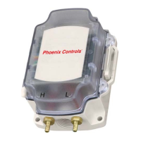
The Fan Static Reset Kit accurately measures the static pressure drop
across a clean air valve and provides feedback to the Building
Management System (BMS) to optimize fan control. The sensor is
housed in a rugged polycarbonate enclosure, which mounts directly to
the valve base channel and has a 3-wire connection to the valve
mounted controller for power and signal. Two pressure pickups, two
pressure dampers and two, six foot lengths of silicon tubing are
included for mounting upstream and downstream of the valve to
obtain optimized pressure readings. One device with a range of 0.0 to
5.0" W.C. covers both medium and low pressure valves and allows for
dynamic fan control to reduce energy consumption under varying
flow conditions.
FEATURES
• Precision sensor provides accurate control feedback value
• Sensor mounts directly on valve base channel
• Pressure value is available network wide
• BMS can dynamically monitor and control fan static
• Maximize energy savings by running fans at lowest possible static
SPECIFICATIONS
Pressure Transmitter
Pressure Range 0 to 5" W.C. (0 to 1.245 Pa)
Output Voltage 0.25 to 4.0 Vdc
Zero Pressure Output 0.25 ±0.06 Vdc
Accuracy 1.5% of span (0.0 to 3.0" W.C. at 75° F)
(0 to 747 Pa at 23.9° C)
2.0% of span (3.0 to 5.0" W.C at 75° F.)
(747 to 1245 Pa at 23.9° C)
Proof Pressure 1 PSI either Port (6.9K Pa)
(performance will be affected)
Burst Pressure 1.5 PSI either Port (10.4K Pa)
(permanent damage will occur)
Corrosion Resistance Pressure sensor is suitable for clean,
non-corrosive, non-condensing air only
Supply Voltage 7 to 32 Vac or 7 to 40 Vdc
Power Consumption 0.12 VA maximum
Storage Temperature 40 °F to 203° F (-40° C to 95° C)
Operating
Temperature
32° F to 140° F (0° C to 60° C)
TABLE OF CONTENTS
Ordering Guide ............................................... 2
Applications ..................................................... 2
Installation....................................................... 3
Wiring the Pressure Sensor............................... 7
Phoenix Controls Wiring Recommendations ... 9
Maintenance .................................................... 9
Troubleshooting ............................................. 10
Phoenix Recommended Wiring ..................... 11