28
7
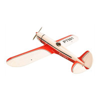
4. Attach and glue the plastic cover for the landing
gear.
1
0
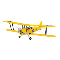
down thrust
3
0
right thrust
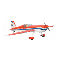
ENGINE INSTALLATION
INSTALLING THE THROTTLE PUSHROD HOUSING
1. Install the engine mount into the fire wall using
4mm x 25mm screw.
2. Place the engine into the engine mount and
align it properly with the front of the cowling.
The distance from the firewall to the front of the
engine thrust washer should 110mm.
If your engine is equipped with a remote needle
valve, we suggest installing it into the engine at
this time.
3. When satisfied with the alignment of the engine,
use a pencil and mark the mounting hole
location onto the firewall, where the throttle
pushrod will exit.
4. Now, remove the engine. Using a 5mm drill bit,
drill holes through the firewall and the forward
bulkhead at the marks made.
5. Slide the pushrod housing through the hole in
the firewall, through the hole in the forward
bulkhead, and into the servo compartment.
6. Apply a couple of drops of thin C/A to the
pushrod housing where it exits the firewall and
where it passes through the forward bulkhead.
This will secure the housing in place.
7. Using a modeling knife, cut off the nylon pushrod
housing 26mm in front of the servo tray.
INSTALLING THE ENGINE
1. Locate the long piece of wire used for the
throttle pushrod. One end of the wire has been
pre-bend in to a "Z" bend at the factory. This
"Z" bend should be inserted into the throttle
arm of the engine when the engine is fitted onto
the engine mount. Fit the engine to the engine
mount using the screws provided.
!
29
110mm
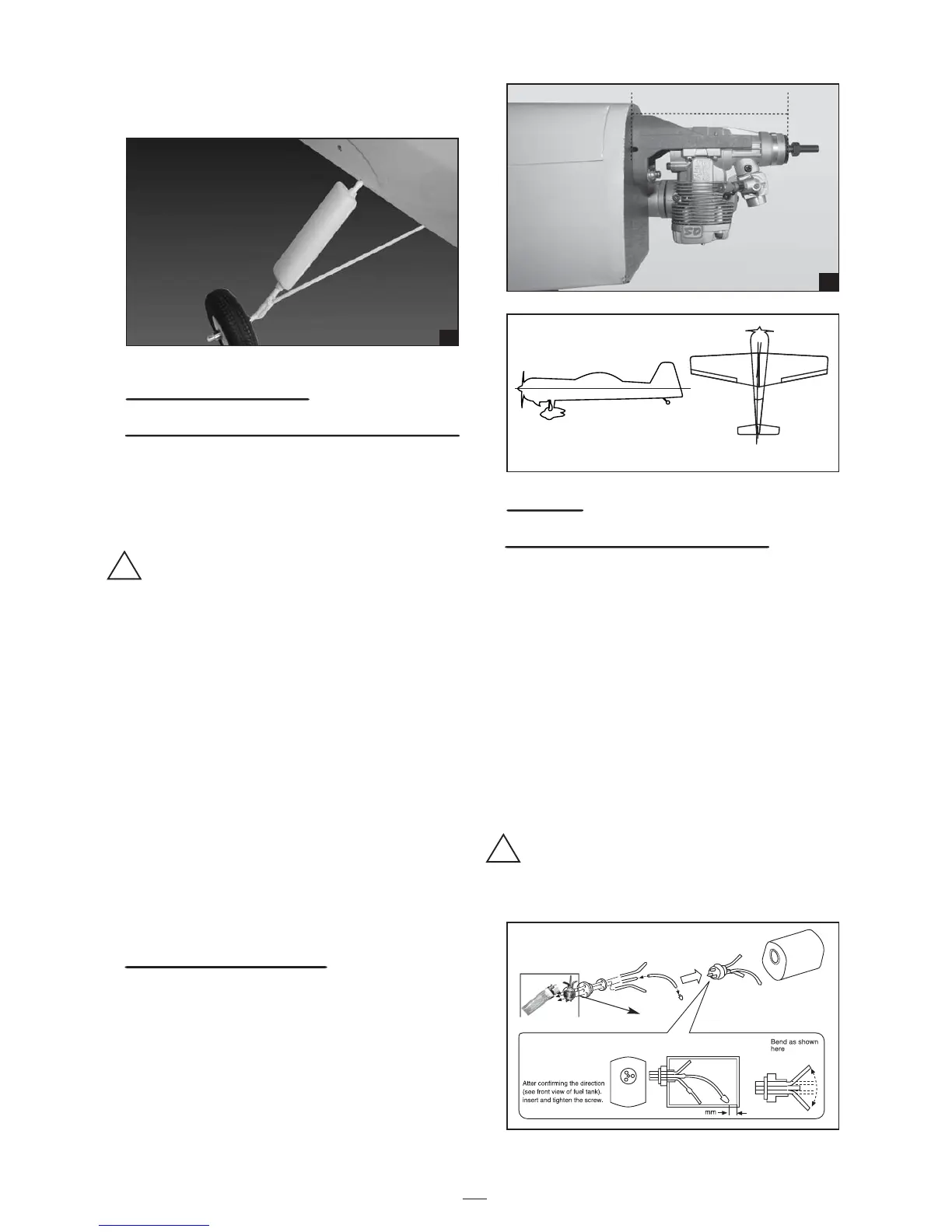
FUEL TANK
INSTALLING THE STOPPER ASSEMBLY
1.
The stopper has been pre-assembled at the factory.
2. Using a modeling knife, cut one length of silicon
fuel line (the length of silicon fuel line is
calculated by how the weighted clunk should
rest about 8mm away from the rear of the tank
and move freely inside the tank). Connect one
end of the line to the weighted clunk and the
other end to the nylon pick up tube in the
stopper.
3. Carefully bend the second nylon tube up at a 45
degree angle (using a cigarette lighter). This
tube will be the vent tube to the muffler.
4. Carefully bend the third nylon tube down at a 45
degree angle (using a cigarette lighter). This
tube will be vent tube to the fueling valve
When the stopper assembly is installed in the
tank, the top of the vent tube should rest just
below the top surface of the tank. It should not
touch the top of the tank.
!
8