10
HELIX BOARD 12 FIREWIRE MKII
33. Program Control
This control is used to scroll through the various
effects. Turning the control clockwise will allow
users to ascend into higher program numbers,
and turning it counter-clockwise will allow users
to descend into lower program numbers. Pushing
this control will apply the new effect. When a tap-
delay effect is selected, pressing this control will
allow users to select the tap-delay time.
By pushing the button several times, the effect
processor interprets the time between last two
pushes and remembers this as the delay time
– until the button is pushed again. This is kept
even after the power is turned off. When the tap
delay effect is selected, a small LED will ash
within the digital effect display window at the
selected intervals.
Master Section
34. AUX Stereo Return Controls
These controls adjust the signal level of audio
fed through to the AUX Stereo Return inputs,
which will be added to the MAIN L-R mix. The
AUX Return 2 control also acts as the built-
in DSP Effect level control, when no device is
plugged into the AUX 2 Return jacks.
35. EFX to Monitor button
This button allows users to select the destination
of the AUX Return 2 signal. Pushing it in sends
the signal to the AUX Send 1 mixing bus.
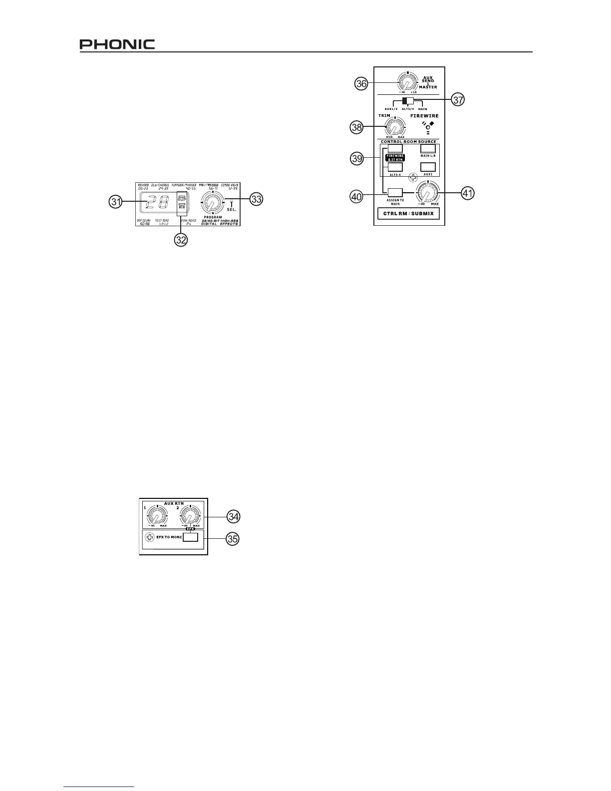
36. AUX Send 1 Master Control
This control will adjust the nal output level for
the AUX send output, the signal of which is taken
from the AUX 1 from each input channel.
37. FireWire Source Select
This switch determines which of teh Helix
Board’s signals will be used for the 9th and 10th
channels sent through the FireWire interface
to the computer. Users can choose to send
the stereo signal from AUX 1/2, Alt 3/4 or the
Main mix through the FireWire interface to the
computer.
38. FireWire Trim Control and Indicator
This trim control can be used to adjust the level
of the outgoing FireWire signal from channel
9/10 (which will be received by the computer). If
the input signals received by your computer are
noticeably excessive, using this control could
help to attenuate the signal to an acceptable
degree. The accompanying LED will illuminate
when a connection is established through the
FireWire interface.
39. Control Room Buttons
Engaging any of these four buttons will enable you
to use the signal from any of the corresponding
sources to send to the Control Room mixing bus
and the LED Level Meter for level monitoring.
For instance, pressing FireWire & 2T Rtn button
will allow you to send the 2 Track Return signal
and the signal received through the FireWire
interface to the Control Room Outputs (the level
of which will be visible on the Level Meter), where
as the Main L-R will allow you to use the Main
Left/Right signal, the AUX 1 allows you to use
the AUX 1 signal, and the ALT 3-4 allows you to
use the “Alternate” stereo mix bus signal. You
can even use a combination of all these signals,
if need be.