Do you have a question about the Phonic MU 1002X and is the answer not in the manual?
Step-by-step guide for initial setup and connection of the mixer.
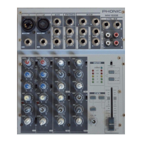
Details on using 3-pin XLR inputs for microphones, including phantom power.
Information on connecting line-level devices via 1/4" TRS or TS jacks.
Explanation of the TRS phone jack for external processors on mono channels.
Usage of stereo channels with dual 1/4" jacks for keyboards and other stereo sources.
Description of the main stereo line level outputs for amplifiers or other devices.
Details on the 1/4" TS inputs for returning processed audio from external sources.
Information about 1/4" TS outputs for connecting to external digital effect processors.
Details on the stereo output port for headphones, controlled by the Phones/Control Room knob.
Description of RCA outputs for connecting to recording devices like MD players or computers.
Explanation of RCA inputs for connecting external devices to the mixing bus.
Location and function of the mixer's main power switch.
Port for connecting the external power supply to the mixer.
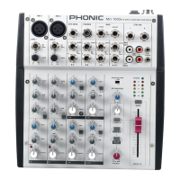
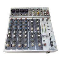
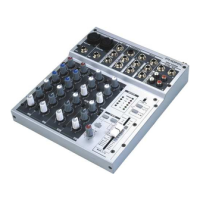
Details on controls for individual input channels.
Adjusts input sensitivity for microphones and line-level signals.
Provides a shelving boost or cut for high frequencies (12 kHz).
Button to reduce frequencies below 75 Hz, removing unwanted noise.
Adjusts middle frequencies for channels.
Adjusts low frequencies for channels.
Controls signal level sent to the EFX SEND output.
Adjusts input sensitivity for different operating levels.
Alternates audio level between left and right channels.
LED indicating when channel signal approaches overload.
Alters channel output level to the main mixing bus.
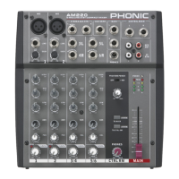
Turns the built-in effect processor on or off.
Indicates when the EFX signal hits high peaks.
Allows selection of one of the 16 built-in digital effects.
Adjusts the main parameter of the selected effect.
Sets the delay time for the tap delay effect.
Adjusts the final level of the EFX mix sent to the Main L-R mix.
Adjusts signal level of audio fed through to AUX Stereo Return inputs.
Selects destination for 2T Return signal to Main L/R or Phones/Ctrl Room.
Sends stereo EFX signal to control room/phones mix with priority.
Activates +48V phantom power for microphone inputs.
Adjusts audio level for phones and control room outputs.
Final level control for the main left and right audio feed.
Converts stereo Main L-R signal into a monaural signal.
Indicates when MAIN L/R output levels reach certain levels.
LED that lights up when the mixer's power is on.
Examples of using the mixer for recording purposes.
Guide on connecting and using external signal processors with the MU1002X.
Instructions for connecting the mixer as an additional unit in a PA system.
Physical dimensions of the MU502 mixer.
Physical dimensions of the MU802 and MU1002X mixers.
Block diagram illustrating the signal flow for the MU502 mixer.
Block diagram illustrating the signal flow for the MU802 mixer.
Block diagram illustrating the signal flow for the MU1002X mixer.
Information on obtaining replacement parts, service, and repairs.
Details on Phonic's product warranty coverage and terms.
Resources for customer support, FAQs, and technical assistance.
| Type | Analog |
|---|---|
| Channels | 10 |
| Phantom Power | Yes |
| USB Interface | No |
| EQ | 3-band EQ on each channel |
| Aux Sends | 1 x Aux Send |
| Returns | 2 |
| Effects | 16 DSP effects |
| Outputs | Main, Control Room, Headphone |
| Line Inputs | 6 |