Do you have a question about the Phonic MM1002 and is the answer not in the manual?
Essential safety instructions to prevent fire, electric shock, and damage to the unit.
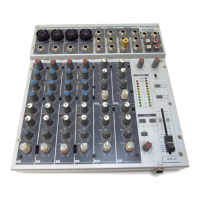
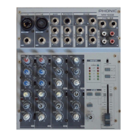
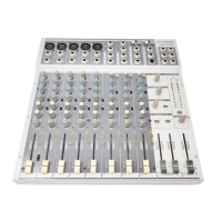
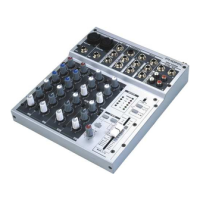
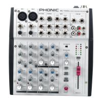
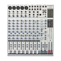
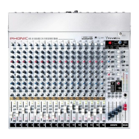
Welcome message, mixer construction overview, and a list of key features for MM1002/MM1202.
Crucial first steps and safety advice for getting started with the mixer's operation.
Illustrates common audio signal flow and connections for microphones, instruments, and outputs.
Diagrams showing various audio cable types, including balanced and unbalanced, and their pinouts.
Explains the characteristics and differences between unbalanced and balanced audio signal transmission.
Provides essential guidelines for proper grounding and wiring to ensure interference-free balanced audio connections.
Details the MIC/LINE selection and GAIN control for optimal input signal adjustment.
Explains HIGH EQ, +48V Phantom Power, and the INSERT point for channel signal path.
Details the MID and LOW EQ controls and the LOW CUT filter for sound shaping.
Explains AUX/EFX sends, PEAK indicator, and PAN control for channel signal routing and monitoring.
Describes the LEVEL fader for output proportion and the M-S switch for stereo recording.
Explains the concept and setup for M-S stereo recording using the mixer's feature.
Explains the cardioid polar pattern, its sensitivity, and applications in sound reinforcement.
Describes the figure-8 polar pattern, its bi-directional sensitivity, and sound rejection.
Details the stereo input jacks and the +4/-10 switch for matching input sensitivities.
Explains the BALANCE control for adjusting stereo image placement in the main mix.
Describes MAIN OUT, EFX OUT, AUX OUT, and CTRL RM outputs for signal routing.
Details REC/2T RTN jacks, EFX/AUX OUT controls, Phantom Power, and metering functions.
Details AUX signal path select, CTRL RM LEVEL, HEADPHONE jack, and MAIN L/R FADER.
Explains the POWER SUPPLY INPUT SOCKET and the POWER ON/OFF SWITCH for unit operation.
Essential pre-setup steps including setting faders, power amps, and headphone levels.
Step-by-step guide for adjusting input gain, applying signal, and monitoring levels for each channel.
Illustrates typical setup for connecting microphones, instruments, and output devices for general use.
Shows a typical connection configuration for a live band performance, including stage monitors.
Provides the physical dimensions (width, height, depth) for the MM1002 model in mm/inch.
Provides the physical dimensions (width, height, depth) for the MM1202 model in mm/inch.
Details the number and type of inputs and outputs for the MM1002 and MM1202 mixers.
Lists features like EQ, Pan, MS matrix, inserts, and master section controls for both models.
Provides technical data on noise levels, frequency response, maximum signal levels, and impedances.
Details impedances, equalization bands, low cut filter, preamp EIN, and power consumption.
Visual representation of the internal signal flow and component architecture for the MM1002 mixer.
Visual representation of the internal signal flow and component architecture for the MM1202 mixer.
A list of recommended books for advanced audio engineering and sound system operation.
| Channels | 10 |
|---|---|
| Mic Inputs | 4 |
| Line Inputs | 6 |
| EQ | 3-band |
| Phantom Power | Yes |
| Master Outputs | 2 |
| Type | Analog Mixer |
| Inputs | 10 |
| Power Supply | External |
| Aux Sends | 1 |
| Headphone Output | 1 |