PHONIC CORPORATION
Page 14
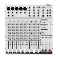
REAR PANEL DESCRIPTION
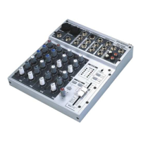
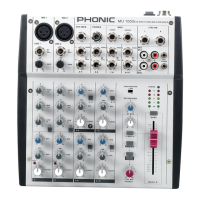
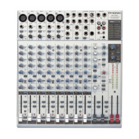
MM1002 / MM1202 USER’S MANUAL
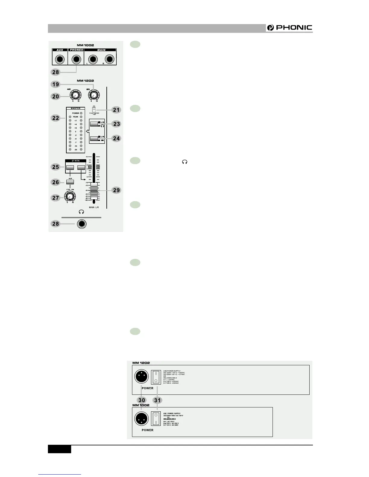
26 AUX SIGNAL PATH SELECT
BUTTON
Push this button to feed the AUX sig-
nal to the control room affected by the
control room level.
27 CTRL RM LEVEL
This rotary fader controls the output
level to the control room and
headphone.
28 HEADPHONE
This jack socket sends the mix sig-
nals to the headphone.
29 MAIN L/R FADER
This 60mm long fader controls the
output level of MAIN OUT.
30 POWER SUPPLY INPUT
SOCKET
Connect the power supply unit to this
socket. Make sure the power supply
unit is not plugged into AC outlet be-
fore connecting to the mixer.
31 POWER ON/OFF SWITCH
This switch turns the power of the unit
on and off.
REAR PANEL DESCRIPTION