Do you have a question about the Phonic Powerpod 7 and is the answer not in the manual?
To reduce the risk of fire or electric shock, do not expose this appliance to rain or moisture.
Water and electricity do not mix. Keep this unit away from water.
Do not attempt to service this unit. Only a qualified service technician should open this unit for servicing.
To reduce the risk of electric shock, do not remove cover (or back). No user-serviceable parts inside.
Keep it clean. Dust, dirt and debris can interfere with the performance of this product.
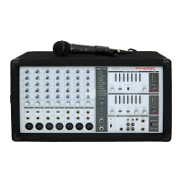
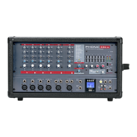
Highlights the key capabilities and components of the Phonic Powerpod 7 mixer.
Lists important safety and operational guidelines for using the Powerpod 7 mixer.
Details the various controls and indicators within the channel strip section of the mixer.
Indicates when the incoming signal level is too high, alerting to potential distortion.
Adjusts the level of the high frequency portion of the sound, offering 15dB boost/cut shelving at 12kHz.
Adjusts middle frequencies, useful for guitar tones or vocal clarity, with 15dB boost/cut peaking at 2.5kHz.
Adjusts low frequencies, offering 15dB boost/cut shelving at 80Hz for bass response.
Controls the amount of signal sent to the Monitor bus.
Varies the amount of signal sent to the effects loop send and the built-in digital effect unit.
Adjusts the output level for each channel.
Attenuates the input signal by 30 dB, useful for line level devices or distorted mic inputs.
Connects instruments like guitars, synths, and drum machines safely, accepting balanced/unbalanced signals.
XLR mic input for low impedance microphones, providing +48 phantom power.
Input jacks for microphones and stereo line level devices, supporting simultaneous use.
Activates the built-in digital effect, sending processed signal to the Main/Monitor bus.
Provides four types of effects: Digital Delay, Vocal Reverb, Large Hall Reverb, and Small Hall Reverb.
Adjusts the effect send level for external devices connected to the Effect Out jack.
Output jack for connecting an external effect device.
1/4" jack for connecting a foot switch to activate/defeat digital effects.
Selects how graphic equalizers and the power amp function as Main/Monitor or Main1/Main2.
Two 7-band graphic equalizers for adjusting Monitor and Main bus signal frequency response.
Adjusts the level of effect sound returned to the Monitor bus.
Indicates the operation of the built-in limiter circuit, preventing excessive input levels.
Monitors signal levels from Monitor Jack (34) or Main Jack (35) depending on selector settings.
Adjusts the final level of the Monitor bus signal to speakers and line output.
Adjusts the level of effect sound returned to the Main bus.
Monitors signal levels output from the Main Jack (35).
Adjusts the final level of the Main bus signal to speakers and line output.
Adjusts the amount of signal sent from Tape In jacks to the Main bus.
Adjusts the amount of signal sent from Aux In jacks to the Main bus.
Indicates when the Powerpod 7 is turned on.
Selects phantom power for XLR mic inputs on Channels 1-4.
Lights when the Phantom Power switch is turned on.
Allows signal from external devices (e.g., effects) to be added to the Main output.
Allow signal from external devices (e.g., cassette recorder) to be added to the Main output.
Alternative main outputs with RCA jacks for connecting to cassette decks and home audio equipment.
Sends Monitor bus signal to external devices, passing through master control and graphic equalizer.
Sends Main bus signal to external devices, passing through master control and graphic equalizer.
Selects output signals for the built-in two-channel power amplifier (Bridge or Main-Main/Monitor).
Jacks for connecting speakers, supporting independent or bridge connections with impedance guidelines.
Switches the Powerpod 7 on and off.
Details voltage gain levels for various inputs and outputs.
Specifies the equalization range for input channels.
Defines the frequency response characteristics for different output types.
States the maximum output power of the amplifier.
Specifies the THD levels for amplifier and main outputs.
Details equivalent input noise and residual output noise levels.
Indicates the level of signal leakage between adjacent inputs.
Specifies the number of bands and range for the graphic equalizer.
Lists the types of built-in digital effects available.
Details the +48V phantom power supply for condenser microphones.
Indicates the output level setting for the limiter LED.
Specifies the function of the foot switch.
States the total power consumption of the unit.
Provides the physical dimensions of the unit.
Specifies the weight of the unit.
| Brand | Phonic |
|---|---|
| Model | Powerpod 7 |
| Category | Music Mixer |
| Language | English |