SECTION 2 - TECHNICAL DESCRIPTION
Page 2.3
PXI/PXIe LVDT/RVDT/Resolver Simulator Module 41/43-670
pickering
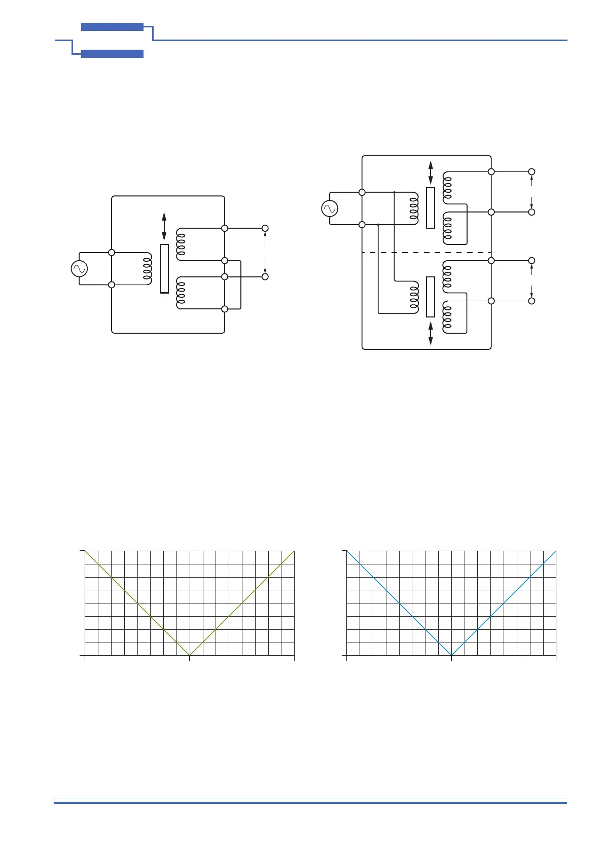
Mode 2 - 4-Wire (Fully Independent Control)
Each bank of the 41/43-670 module can be congured to simulate 4-wire operation of an LVDT as shown in the
left hand diagram below. Additionally, the A and B channels of one bank of the 41/43-670 module can be used as
separately controlled 4-wire simulation outputs with a common excitation signal as shown in the right hand diagram:
Output
Voltage
Core Displacement
-100% +100%
V
0
0
Output A
Phase Invert
Output
Voltage
Core Displacement
-100% +100%
V
0
0
Output B
Phase Invert
Figure 2.4 - 4-Wire Operation of an LVDT
Figure 2.5 - Voltage Output for Core Displacement for 4-Wire LVDTs
In this mode the two outputs of the bank are controlled fully independently allowing simulation of two separate
4-wire LVDTs on each bank, the output will be the equivalent of combining both outputs of the 5/6 wire mode with
the computation carried out internally.
VOutA = VA – VB VOutB = VA – VB
The 41/43-670’s 4-Wire Mode 2 gives better accuracy than combining two outputs of the 5/6-Wire Mode 1, also as
two independent LVDTs can be simulated per bank better density is achieved.
The output at 0% will be zero (null position), in the positive direction the output will have an inverted phase.
To congure the LVDT simulation banks to the desired modes please refer to the Programming Guide in Section 5.
VOUT=VA-VB
LVDT 4-Wire Operation - Differential Output
in
out A
out B
Excitation
Primary
Secondary
Secondary
Core
Displacement
LVDT
VOUT2
41-670 Module 4-Wire Operation - Independent Outputs
(Two Independent Channels - Common Excitation)
VOUT1
in
out A
out B
Excitation
Primary
Secondary
Secondary
Primary
Core
Core
Displacement
Displacement