Page 2.2
SECTION 2 - TECHNICAL DESCRIPTION
PXI/PXIe LVDT/RVDT/Resolver Simulator Module 41/43-670
pickering
SIMULATION CONFIGURATIONS
The 41/43-670 Simulator has up to 4 banks with consisting of four inputs and eight outputs, which may be set into
different modes of operation:
• Mode 1 - 5/6-Wire (2 complementary outputs)
• Mode 2 - 4-Wire (2 independently controllable outputs)
Mode 1 - 5/6-Wire (Complementary Control)
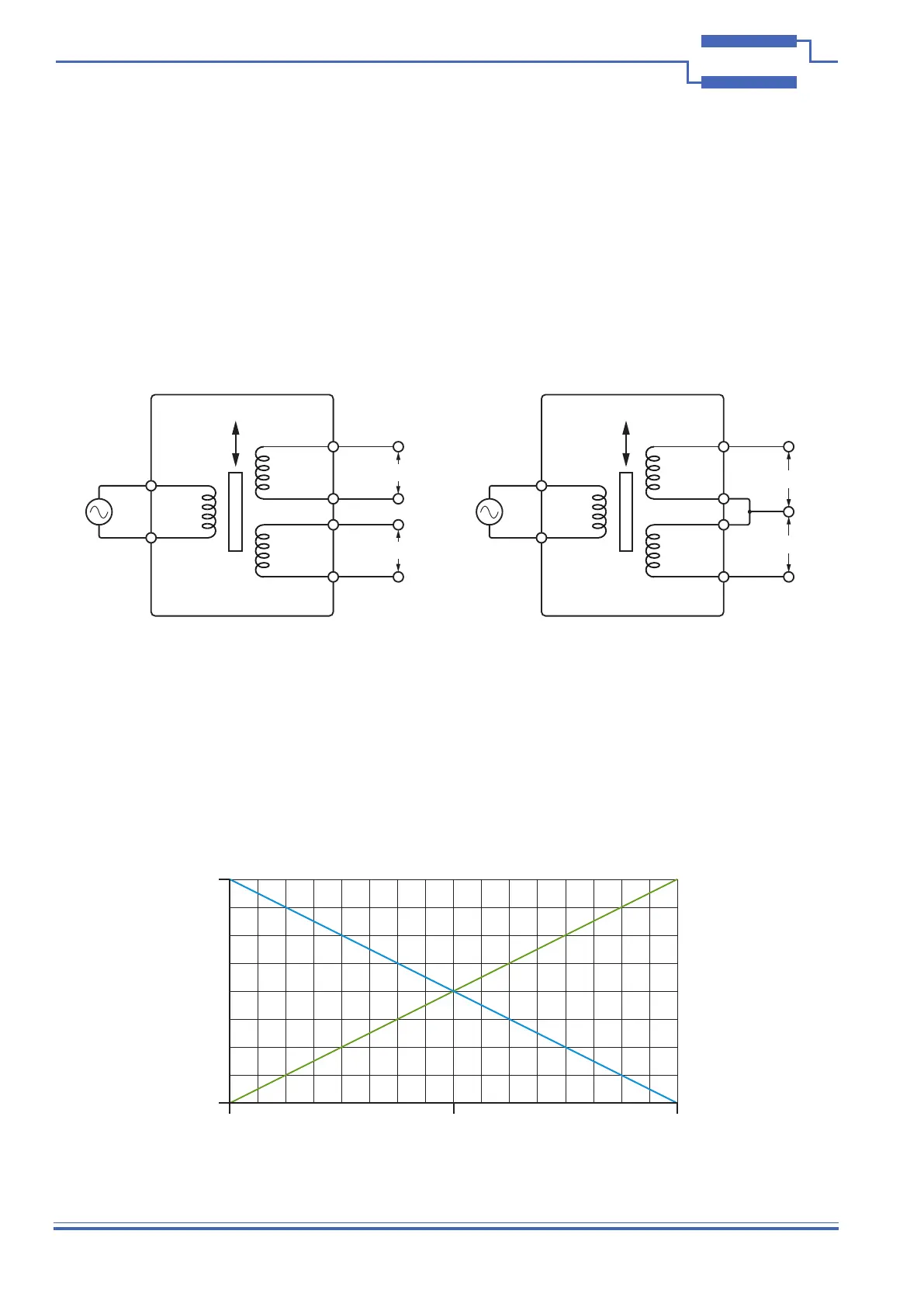
Each bank of the 41/43-670 module can be congured to simulate 5 and 6-wire operation of an LVDT as shown in
the diagrams below:
6-Wire Operation - Complimentary Outputs
in
out A
out B
Excitation
VB
5-Wire Operation - Complimentary Outputs
VA
VB
VA
Primary
Secondary
Secondary
Core
Displacement
in
out A
out B
Excitation
Primary
Secondary
Secondary
Core
Displacement
LVDT LVDT
Output
Voltage
Core Displacement
-100% +100%
V
0
0
Output A
Output B
Figure 2.2 - 6 and 5-Wire Operation of an LVDT
Figure 2.3 - Voltage Output for Core Displacement for 5 and 6-Wire LVDTs
For 5 and 6-wire operation of an LVDT, the A and B outputs are complementary; VA + VB = Vsum
As the amplitude of output A increases, output B decreases in amplitude by the same amount. This is illustrated in
the graph below: