Page 4.20
SECTION 4 - PROGRAMMING GUIDE
PXI/PXIe LVDT/RVDT/Resolver Simulator Module 41/43-670
pickering
PROGRAMMING THE INPUT/OUTPUT SWITCHES
Each LVDT simulation bank has switches on the inputs and output to enable short and open circuit conditions
for fault simulation. Also switching is included for interconnecting inputs so that a common excitation signal can
be shared between channels. These switches can be controlled graphically using the Soft Front Panel, or the
corresponding bits can be set via the appropriate sub-unit using the module’s driver. The sub-unit and bit allocations
for these switches is summarized in the following table and in Figure 4.15.
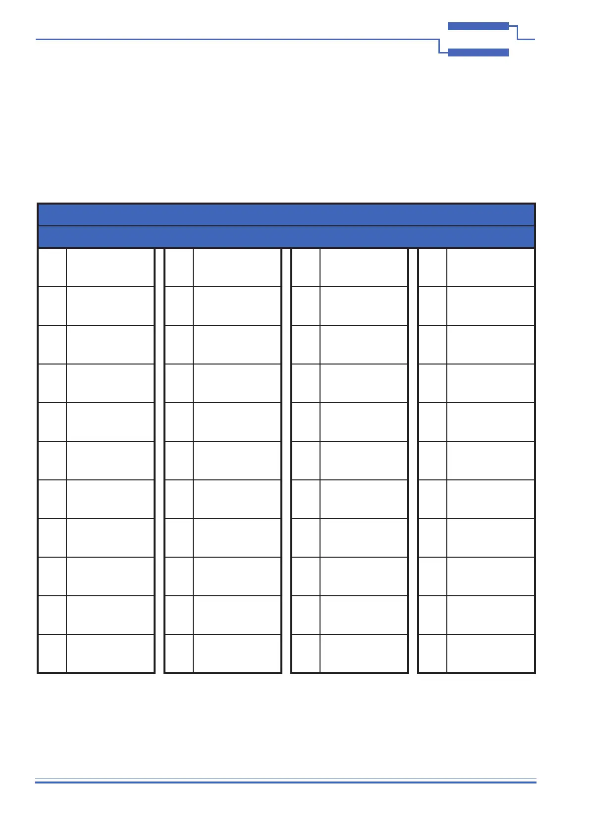
Table 4.1 Sub-unit/Bit Usage for Input and Output Switches
Sub-unit 5
Bit Switch Function Bit Switch Function Bit Switch Function Bit Switch Function
1
Channel 1:
IN_S_1
12
Channel 2:
IN_S_2
23
Channel 3:
IN_S_3
34
Channel 4:
IN_S_4
2
Channel 1:
IN_G_1
13
Channel 2:
IN_G_2
24
Channel 3:
IN_G_3
35
Channel 4:
IN_G_4
3
Channel 1:
IN_S_1 break
14
Channel 2:
IN_S_2 break
25
Channel 3:
IN_S_3 break
36
Channel 4:
IN_S_4 break
4
Channel 1:
IN_S_1 &
IN_G_1 short
15
Channel 2:
IN_S_2 &
IN_G_2 short
26
Channel 3:
IN_S_3 &
IN_G_3 short
37
Channel 4:
IN_S_4 &
IN_G_4 short
5
Channel 1:
OUTA_S_1
16
Channel 2:
OUTA_S_2
27
Channel 3:
OUTA_S_3
38
Channel 4:
OUTA_S_4
6
Channel 1:
OUTA_G_1
17
Channel 2:
OUTA_G_2
28
Channel 3:
OUTA_G_3
39
Channel 4:
OUTA_G_4
7
Channel 1:
OUTA_S_1 &
OUTA_G_1 short
18
Channel 2:
OUTA_S_2 &
OUTA_G_2 short
29
Channel 3:
OUTA_S_3 &
OUTA_G_3 short
40
Channel 4:
OUTA_S_4 &
OUTA_G_4 short
8
Channel 1:
OUTB_S_1
19
Channel 2:
OUTB_S_2
30
Channel 3:
OUTB_S_3
41
Channel 4:
OUTB_S_4
9
Channel 1:
OUTB_G_1
20
Channel 2:
OUTB_G_2
31
Channel 3:
OUTB_G_3
42
Channel 4:
OUTB_G_4
10
Channel 1:
OUTB_S_1 &
OUTB_G_1 short
21
Channel 2:
OUTB_S_2 &
OUTB_G_2 short
32
Channel 3:
OUTB_S_3 &
OUTB_G_3 short
43
Channel 4:
OUTB_S_4 &
OUTB_G_4 short
11
Channel 1:
IN_S_1 to BUS*
22
Channel 2:
IN_S_2 to BUS*
33
Channel 3:
IN_S_3 to BUS*
44
Channel 4:
IN_S_4 to BUS*
*The BUS connection allows channels to share the same input signal.