© 2019 Pierce Manufacturing Inc. All Rights Reserved. Pierce Pumper / 2-1
Chapter 2 BEFORE PLACING IN SERVICE
Pump Chart and Intake Relief Valve
2-1. Create a Pump Chart
Use a Pump Chart to determine the pump discharge pressure that will provide desired nozzle pressure for various
hose lay configurations and combinations.
The IFSTA Pumping Apparatus Driver/Operator Handbook tells how to develop a pump chart. Develop the chart for
all situations.
Make sure this chart is always available during pump operation.
2-2. Check Adjustment of Intake Relief Valve
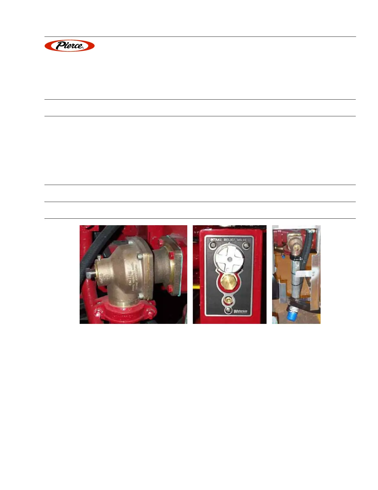
Figure 2-1: Typical Intake Relief Valve (relief outlet pipe with threaded end shown on right)
POM0016, 0017, 0018
All pumps have a relief valve on the intake side (Figure 2-1). It prevents a pressure spike in intake water from
passing to hoses through the discharge side of the pump.
The intake relief valve is a pressure regulator. If intake pressure goes over the pressure setting, the valve opens and
allows water to flow out the relief outlet.
Some departments choose to connect a hose to the relief valve outlet to direct the water discharge away from the
apparatus. Pressure surges in this hose can occur without warning.