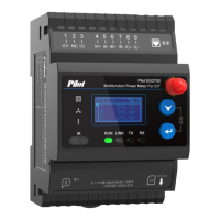
9.3 Terminal specification table
Note: The order of RJ45 from left to right is :The first circuit temperature positive, the
first circuit temperature is negative, the second circuit positive, the second circuit
temperature, the third circuit positive, the third circuit negative, the fourth circuit
positive, and the fourth circuit negative.
9.4 Terminal wiring instructions
9.4.1 Communications wiring
(1) RS-485 communication port, the terminals are marked as 485A+, 485B+.
The RS-485 communication mode allows up to 32 PMC series meters to be
connected to one bus, connected to the host computer through an RS-232/RS-485
converter. Communication cables can use ordinary shielded twisted-pair cables, and
the total length should not exceed 1200 meters. The positive and negative polarity of
the RS-485 ports of each device must be connected correctly, and one end of the cable
shielding layer must be grounded. If the shielded twisted pair is long, it is
recommended to connect a resistance of about 120Ω at its end to improve the
reliability of communication. For the convenience of on-site connection, the positive
and negative polarity of the RS-485 port has two connection ports, and the
communication connection is as follows:
A phase current
input line
B phase current
input line
C phase current
input line
Leakage current into the
line
A phase current
output line
Leakage current
outgoing the line
B phase current
output line
Switch volume 1 input
positive
C phase current
output line
Switch input common
terminal

 Loading...