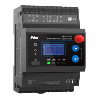
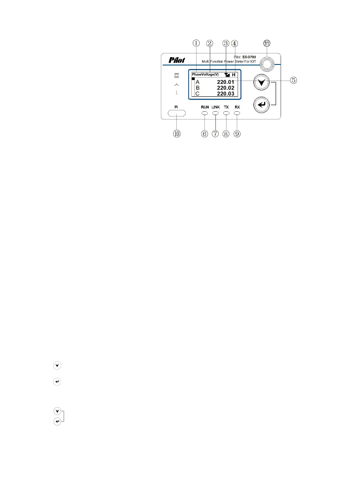
4.2 All show figure
1
、
Function title;
2
、
Unit display area;
3
、
4G signal display icon;
4
、
The 4G signal strength;
5
、
Main data display area;
6
、
Running indicator light: Flashing while running;
7
、
Network connection light: always on when connected to the Internet;
8
、
RS485/Lora sending indicator light: flashing when the device sends;
9
、
RS485/Lora receiving indicator light: flashing when the device receives;
10
、
Infrared transceiver;
11
、
Antenna connector.
Note:
If there is no button operation on the homepage in 180s, the screen will be off
and the screen will not be lit again until there is a button pressed. If there is no button
pressed on other pages in 180s, the screen will jump to the homepage.
4.3 Button instruction
In different interfaces, the same button has different functions.
Next key: Change value when switching/programming in peer menu
Enter key: Move the cursor to the left when switching submenus/programming in
the peer menu
Key combination: Ruturn/Switching between real-time pages and programming
pages
 Loading...