Do you have a question about the Pilot Communications SPM90 and is the answer not in the manual?
Presents the physical dimensions of the SPM90 DC energy meter and its components.
Illustrates the mounting of the SPM90 DC meter on a DIN rail and shunt dimensions.
Details the SPM90's one-inch dot matrix LCD screen, resolution, and backlight behavior.
Describes the indicator light status, color, and its meaning for electric energy pulse.
Explains the operation of the two keys for menu navigation and action confirmation.
Details the menu tree and navigation steps for accessing data and settings on the SPM90.
Explains the initial startup sequence and the main menu display after the meter powers on.
Describes how to program the SPM90 meter, including communication protocol and settings.
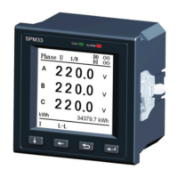
Lists the real-time electrical parameters measured by the SPM90 and their ranges.
Details the maximum energy measurement capacity and rollover behavior of the SPM90.
Specifies the pulse width and pulse constant for electric energy pulse output.
Introduces the SPM90's RS485 communication capabilities and wiring considerations.
Specifies the wire type, maximum number of devices, and distance for RS485 networks.
Details the supported communication protocols, MODBUS-RTU and DL/T 645-2007.
Explains essential parameters like meter address ID and baud rate for communication.
Describes the meter's protection against strong electricity on the communication port.
Provides a clear definition and description for each terminal on the SPM90 meter.
Illustrates standard wiring configurations for the SPM90-1-P model, including connections to shunt and load.
| Brand | Pilot Communications |
|---|---|
| Model | SPM90 |
| Category | Measuring Instruments |
| Language | English |