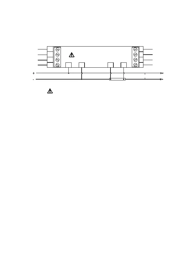
8.2 Typical Wiring Diagram
Wiring of SPM90-1-P is as follows:
12
11
10
9
8
7
6
5
3
4
21
V- input
Shunt
LOAD
PULSE+
PULSE-
NC
NC
POW+
POW-
485B
485A
V+ input
No Incorrect Connection !
Between A and B point, do not connect any other device !
A B
Note:
1. If -P is not included in order, then terminal 9, 10, 11, 12 are not added
on the meter.
2. When installing and wiring, meter shall work with the shunt in the
same package. Otherwise, measuring accuracy will be influenced.
3. The current sampling circuit must be connected to the SPM90 and
cannot be mixed with other device. That is, it is not allowed to connect
any other device between A and B point in the above figure to prevent
damage to the instrument due to voltage circuit.