19
When there has no operation in 3 minutes, the display will automatically turn to
Phase A voltage interface.
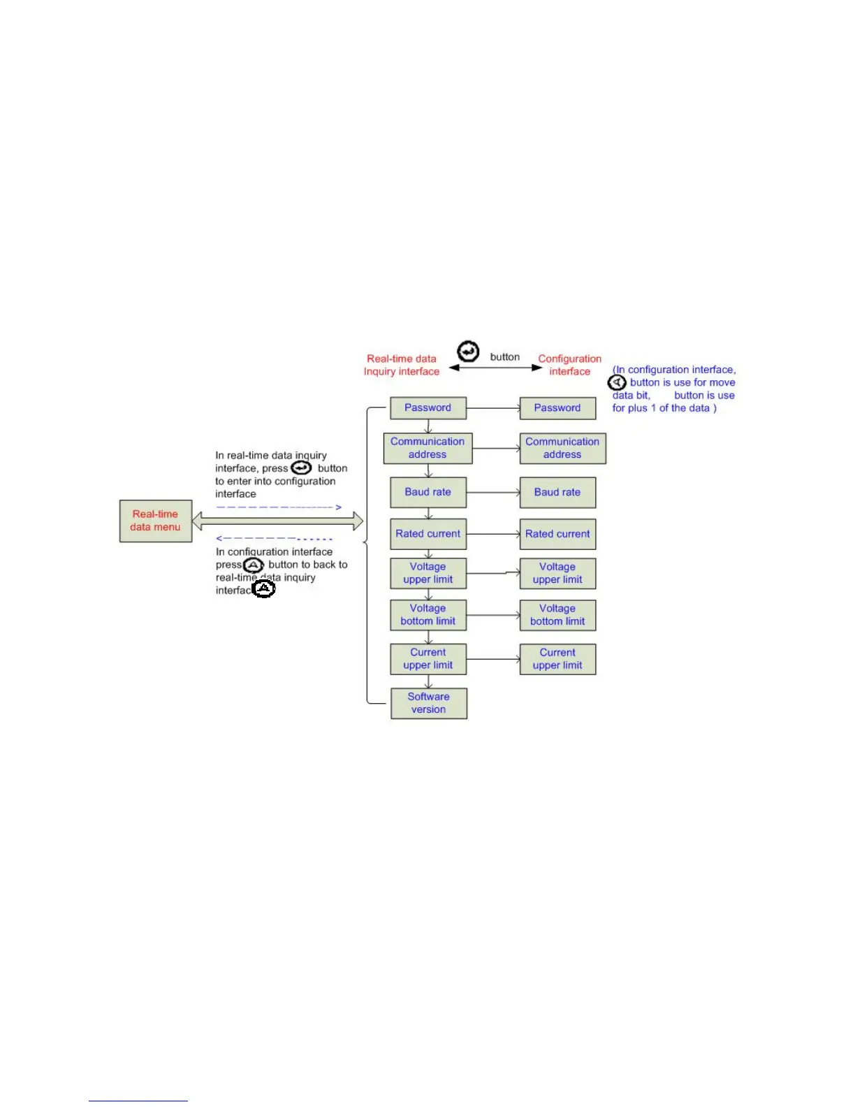
5.4 Parameter configuration
Below is the structure for parameter configuration interface , from real-time
inquiry to parameter configuration interface: