- 1 -
Safety Regulations
• The unit may only be installed and
operated by personnel who are familiar
with both these instructions and the current
regulations for safety at work and accident
prevention. Follow VDE and local
regulations especially as regards
preventative measures.
•
Transport, storage and operating
conditions should all conform to
EN 60068-2-6
• Any guarantee is void following opening of
the housing or unauthorised modifications.
• The unit should be panel mounted,
otherwise dampness or dust could lead to
function impairment.
• Adequate protection must be provided on
all output contacts especially with
capacitive and inductive loads.
• Note for overvoltage category III:
If voltages higher than low voltage
(>50 VAC or >120 VDC) are present on
the unit, connected control elements and
sensors must have a rated insulation
voltage of at least 250 V.
Sicherheitsbestimmungen
• Das Gerät darf nur von Personen installiert
und in Betrieb genommen werden, die mit
dieser Betriebsanleitung und den gel-
tenden Vorschriften über Arbeitssicherheit
und Unfallverhütung vertraut sind.
Beachten Sie die VDE- sowie die örtlichen
Vorschriften, insbesondere hinsichtlich
Schutzmaßnahmen.
• Beim Transport, der Lagerung und im
Betrieb die Bedingungen nach EN 60068-
2-6 einhalten (s. technische Daten).
• Durch Öffnen des Gehäuses oder eigen-
mächtige Umbauten erlischt jegliche Ge-
währleistung.
• Montieren Sie das Gerät in einen Schalt-
schrank; Staub und Feuchtigkeit können
sonst zu Beeinträchtigungen der Funktio-
nen führen.
• Sorgen Sie an allen Ausgangskontakten
bei kapazitiven und induktiven Lasten für
eine ausreichende Schutzbeschaltung.
• Hinweis für Überspannungskategorie III:
Wenn am Gerät höhere Spannungen als
Kleinspannung (>50 V AC oder
>120 V DC) anliegen, müssen angeschlos-
sene Bedienelemente und Sensoren eine
Bemessungsisolationsspannung von mind.
250 V aufweisen.
Conseils préliminaires
• La mise en oeuvre de l’appareil doit être
effectuée par une personne spécialisée en
installations électriques, en tenant compte
des prescriptions des différentes normes
applicables (NF, EN, VDE...) notamment
au niveau des risques encourus en cas de
défaillance de l’équipement électrique.
• Respecter les exigences de la norme
EN 60068-2-6 lors du transport, du
stockage et de l'utilisation de l'appareil.
• L’ouverture de l’appareil ou sa modification
annule automatiquement la garantie.
• L’appareil doit être monté dans une ar-
moire; l’humidité et la poussière pouvant
entraîner des aléas de fonctionnement.
• Vérifiez que le pouvoir de coupure des
contacts de sortie est suffisant en cas de
circuits capacitifs ou inductifs.
• Remarque relative à la catégorie de
surtensions III :
Si l’appareil est alimenté avec des tensions
supérieures à la basse tension (>50 V AC
ou >120 V DC), les éléments de commande
et les capteurs raccordés doivent supporter
une tension d’isolement assignée d’au
moins 250 V.
Bestimmungsgemäße Verwendung
Das Sicherheitsschaltgerät dient dem
sicherheitsgerichteten Unterbrechen eines
Sicherheitsstromkreises. Das Sicherheits-
schaltgerät erfüllt Forderungen der
EN 60947-5-1, EN 60204-1 und VDE 0113-
1 und darf eingesetzt werden in Anwendun-
gen mit
• Not-Halt-Tastern
• Schutztüren
Das Gerät ist nicht für die Absicherung von
berührungslosen Verdeckungen geeignet,
da kein dynamischer Start möglich ist.
Beachten Sie unbedingt die Sicherheitsab-
stände nach EN 294 und die Mindestab-
stände nach EN 349.
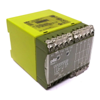
Gerätebeschreibung
Das Sicherheitsschaltgerät PNOZ X2.5P ist
in einem S-99-Gehäuse untergebracht. Die
Versorgungsspannung beträgt 24 V DC.
Merkmale:
• Relaisausgänge: 2 Sicherheitskontakte
(Schließer), zwangsgeführt
• Anschlussmöglichkeit für Not-Halt-Taster,
Schutztürgrenztaster und Starttaster
• Statusanzeigen
• 1 Halbleiterausgang
• Überwachung externer Schütze möglich
• keine galvanische Trennung
Das Schaltgerät erfüllt folgende Sicherheits-
anforderungen:
• Schaltung ist redundant mit Selbstüberwa-
chung aufgebaut.
• Sicherheitseinrichtung bleibt auch bei Aus-
fall eines Bauteils wirksam.
Domaines d’utilisation
Le bloc logique de sécurité sert à
interrompre en toute sécurité un circuit de
sécurité. Le bloc logique de sécurité satisfait
aux exigences des normes EN 60947-5-1,
EN 60204-1 et VDE 0113-1 et peut être
utilisé dans des applications avec des
• poussoirs d'arrêt d'urgence
• protecteurs mobiles
Le relais n’est pas adapté pour la
surveillance de barrages immatériels car un
réarmement dynamique n’est pas possible.
Veuillez respecter impérativement les
distances de sécurité d’après la
norme EN 294 et les distances minimales
d’après la norme EN 349.
Description de l’appareil
Inséré dans un boîtier S-99, le bloc logique
de sécurité PNOZ X2.5P est alimenté en
24 V DC.
Particularités :
• Sorties disponibles : 2 contacts à
fermeture de sécurité
• Bornes de raccordement pour poussoirs
AU, détecteurs de position et poussoir de
validation
• LEDs de visualisation
• 1 Sortie statique
• Auto-contrôle des contacteurs externes
possible
• pas d'isolation galvanique
Le relais PNOZ X2.5P répond aux exigences
suivantes :
• conception redondante avec auto-
surveillance
Authorised Applications
The safety relay provides a safety-related
interruption of a safety circuit. The safety
relay meets the requirements of EN 60947-5-
1, EN 60204-1 and VDE 0113-1 and may be
used in applications with
• E-STOP pushbuttons
• Safety gates
The unit is not suitable for use with non-
contact guards, e.g. ESPE as a dynamic start
is not possible.
Safety distances in accordance with EN 294
and minimum distances in accordance with
EN 349 must be observed.
Description
The Safety Relay PNOZ X2.5P is enclosed in
a S-99 housing. The version available is for
24 V DC operation only.
Features:
• Relay outputs: 2 safety contacts (N/O),
positive-guided
• Connections for Emergency Stop Button,
Safety Gate Limit Switch and Reset button
• Status Indicators
• 1 Semiconductor output
• Feedback Control Loop for monitoring of
external contactors/relays possible
• No galvanic separation
The relay complies with the following safety
requirements:
• The circuit is redundant with built-in self-
monitoring.
20407-6NL-06
PNOZ X2.5P
4 D Betriebsanleitung
4 GB Operating instructions
4 F Manuel d'utilisation
4 E Instrucciones de uso
4 I Istruzioni per l`uso
4 NL Gebruiksaanwijzing