Do you have a question about the Pilz PNOZ X3 and is the answer not in the manual?
Specifies the manual's validity period and update policy.
Provides guidance on how to effectively read and use the manual.
Explains the meaning of important warning and information symbols used.
Details the product's designated applications and compliance with relevant standards.
Outlines essential safety regulations and compliance requirements for operation.
Specifies the qualifications and responsibilities of personnel operating the device.
Conditions under which warranty and liability are invalidated.
Instructions for proper disposal of the electronic device.
Highlights critical safety notes, including overvoltage category considerations.
Describes the types and characteristics of the unit's relay outputs and connections.
Explains built-in redundancy, self-monitoring, and automatic testing for enhanced safety.
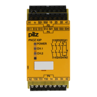
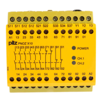
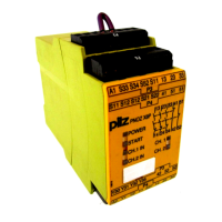
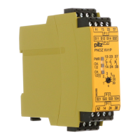
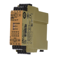
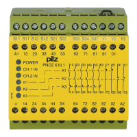
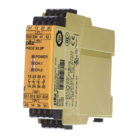
Illustrates the physical layout of the unit's terminals and their functions.
Explains the different operating modes, including single-channel and dual-channel.
Describes the automatic and monitored start functionalities of the unit.
Visual representation of signal timing for various operational states.
Specifies requirements for installing the unit within a control cabinet.
Clarifies the safe use of output contacts and auxiliary contacts.
Recommends appropriate fuse protection for output contacts to prevent welding.
Details a crucial test procedure for detecting shorts across input contacts.
Shows the correct wiring for AC and DC supply voltage connections.
Illustrates wiring configurations for E-STOP and safety gates.
Wiring diagrams for automatic and monitored start circuits.
Shows how to wire feedback loops using external contactors.
Explains the meaning of the unit's LED indicators for status and errors.
Emphasizes the importance of periodic safety function checks by qualified personnel.
Describes the unit's behavior and recovery process for earth faults.
Explains issues related to contact welding and their impact on operation.
Provides the external physical measurements of the unit in millimeters.
Covers supply voltage, current, tolerance, and output power specifications.
Details input circuit voltage, current, and resistance requirements.
Provides ratings for safety and auxiliary relay outputs.
Defines utilisation categories according to EN and UL standards.
Details fuse protection, thermal current, and contact material specifications.
Lists switch-on delay, de-energisation delay, and recovery times.
Covers climatic suitability, temperature, humidity, and EMC.
Includes mounting, material, dimensions, and conductor connection details.
Details PL, SIL, PFH, and PFD values for different operating modes.
Stresses the necessity of complying with safety characteristic data for plant safety.
Advises considering service life graphs for the validity of characteristic data.
Explains factors influencing the PFH value and its interpretation.
Illustrates the relationship between switching current and the number of cycles to wear.
Lists product types, features, connection types, and corresponding order numbers.
Confirms product compliance with the EU Machinery Directive.
Provides contact details for technical support across various regions.
Lists the main international hotline number and email for support.
| Supply Voltage | 24 V DC |
|---|---|
| Contacts | 3 N/O, 1 N/C |
| Width | 45 mm |
| Depth | 121 mm |
| Safety Category | 4 |
| Performance Level | e |
| SILCL | 3 |
| Rated Current | 6 A |
| Contact Material | AgSnO2 |
| Protection Class | IP20 |
| Weight | 200 g |
| Stop Category | 0 |
| Operating Temperature Range | -10°C to 55°C |