Do you have a question about the Pilz PNOZ X10.1 and is the answer not in the manual?
States the validity period of the documentation for the PNOZ X10.1.
Provides guidance on using the manual for installation and future reference.
Explains the meaning of DANGER, WARNING, CAUTION, and NOTICE symbols used in the manual.
Describes the safety relay's purpose, applications, and improper uses.
Mentions the requirement for a safety assessment and meeting directives.
Explains that individual component safety must meet overall plant/machine safety.
Specifies that only competent persons should assemble, install, and operate the product.
Outlines conditions that invalidate warranty and liability claims.
Advises compliance with local regulations for electronic device disposal.
Highlights specific safety notes, like overvoltage category requirements.
Details the safety relay's redundancy, self-monitoring, and automatic testing.
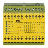
Shows the wiring diagram and terminal layout for AC types.
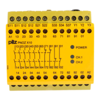
Presents the terminal configuration and wiring diagram for DC types.
Explains the operating principle, LED indicators, and contact states.
Describes single-channel and dual-channel operation modes with fault detection.
Unit becomes active once the input circuit is closed.
Unit becomes active when input and start circuits are closed.
Unit becomes active after specific input and start circuit sequences.
Illustrates the operational timing for different start modes.
Details a crucial test procedure for the shorts detection function.
Shows connection diagrams for AC and DC supply voltages.
Provides wiring diagrams for various E-STOP and safety gate configurations.
Illustrates wiring for automatic, manual, and monitored start circuits.
Shows diagrams for feedback loop connections, with and without monitoring.
Important note about linking Y1 and S37 for automatic/manual start.
Emphasizes periodic safety function checks by qualified personnel.
Describes common faults like earth faults and contact malfunctions.
Provides physical dimensions of the unit with a diagram.
Lists certifications and general electrical data for the product.
Details input specifications like voltage, current, and resistance.
Covers output contact types, counts, and short circuit current.
Specifies utilisation categories for safety and auxiliary contacts according to standards.
Details UL utilisation categories, pilot duty, and fuse protection.
Specifies the material used for the relay contacts.
Lists thermal current ratings based on the number of loaded contacts.
Provides detailed timing specifications for switch-on and de-energisation delays.
Covers suitability for climate conditions and temperature ranges.
Details humidity, EMC compliance, and vibration resistance.
Specifies overvoltage category, pollution degree, and insulation ratings.
Lists mounting, material, connection types, and conductor cross-sections.
States the weight of the product.
Presents safety integrity levels (SIL) and performance levels (PL) according to standards.
Illustrates relay output cycles vs. switching current for different utilisation categories.
Confirms product compliance with EU machinery directive and provides representative details.
Lists contact information for technical support worldwide.