Do you have a question about the Pilz PNOZ X10 and is the answer not in the manual?
Confirms the current manual's validity period until new documentation is published.
Provides guidance on how to effectively use the manual for installation and commissioning.
Explains the meaning of different symbols used to highlight important information.
Details the primary safety-related function and applications for the PNOZ X10 safety relay.
Outlines requirements for safety assessment and compliance with relevant directives like Machinery Directive.
Specifies the qualifications and responsibilities of personnel involved in assembly, installation, and operation.
Lists conditions under which warranty and liability claims may be rendered invalid.
Provides guidance on product disposal and essential safety notes, including overvoltage category.
Details the key hardware features, including relay outputs and connection options.
Explains the built-in safety mechanisms such as redundancy and self-monitoring.
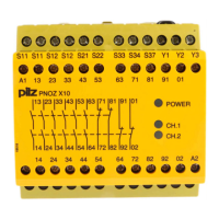
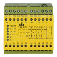
Presents the electrical schematic and terminal layout for AC voltage types.
Describes the basic operation of the safety relay and its response to input circuit status.
Details the different modes of operation like single-channel, dual-channel, automatic, and manual start.
Illustrates the timing sequences for various operational modes and delays.
Provides instructions for operational checks, including safety contact verification.
Specifies requirements for mounting the unit in a control cabinet and on a DIN rail.
Provides essential notes and precautions for connecting the safety relay's circuits.
Details the procedure and importance of testing shorts detection functionality.
Illustrates connection diagrams for AC and DC supply voltages.
Shows wiring configurations for E-STOP, safety gates, and light guards.
Presents wiring diagrams for automatic, manual, and monitored start circuits.
Explains wiring options for feedback loop monitoring with external contactors.
Describes the meaning of the POWER, CH.1, and CH.2 LEDs during operation.
Details common faults like earth faults, contact malfunctions, and LED status during errors.
Provides general information and certifications for the specified order numbers.
Details supply voltage, frequency range, and duty cycle for AC types.
Specifies input circuit voltage, current ratings, and maximum cable resistance.
Lists the number of safety and auxiliary contacts and max short circuit current.
Details utilisation categories for safety and auxiliary contacts under AC and DC loads.
Covers fuse protection requirements and the contact material used.
Specifies various timing parameters like switch-on delay and de-energisation delay.
Lists operating conditions, EMC compliance, vibration, and mechanical properties.
Details supply voltage (AC/DC), input voltage, current ratings, and cable resistance.
Covers relay output types, utilisation categories for safety and auxiliary contacts.
Specifies timing parameters like switch-on delay and de-energisation for DC models.
Lists environmental conditions, EMC compliance, and mechanical properties for DC models.
Presents safety data including SIL, PL, PFH, and PFD values for different operating modes.
Illustrates relay output service life based on switching current and load types.
Provides an example of how to use the service life graph for application planning.
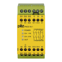
Lists the different PNOZ X10 product types, their features, and corresponding order numbers.
| Type | Safety relay |
|---|---|
| Supply voltage | 24 V DC |
| Number of safety outputs | 2 |
| Safety category | 4 |
| Contact configuration | 2 NO |
| Operating temperature range | -20 °C to +55 °C |
| Stop category | 0 |
| Width | 45 mm |
| Number of contacts | 4 |
| Rated operational current | 6 A |
| Response time | 20 ms |
| Mounting type | DIN rail |
| Standards | EN 60947-5-1, EN 60204-1, EN ISO 13849-1 |